Effects of Secondary Suspension Imbalance on Wheel-Climb Derailment (Part 2 of 2)
By Radovan Sarunac and Peter Klauser • October 2007
Part 1 of this article examined the effects of track geometry, wheel/rail profiles, friction, and wheel flange angle on wheel-climb derailment potential. Part 2 examines the effects of wheel unloading due to air spring imbalance on derailment potential.
The secondary suspension of a modern rail car, which incorporates two air springs per truck and a four-point leveling system, has the potential for a diagonal air spring load imbalance. When this happens, air spring loads and pressures are increased at two diagonal corners, and reduced at the opposing corners, resulting in reduced vertical wheel loads.
In this study, vehicle dynamics and an actual derailment were modeled using a VAMPIRE® vehicle dynamics simulation program. The modeled vehicle was based on a vehicle equipped with powered two-axle, articulated frame trucks. Typical worn wheel and rail profiles were used.
A nominal case was established to evaluate the response of the vehicle without air spring diagonal load imbalance, but with a realistic amount of carbody weight imbalance. The individual and combined effects of air spring load imbalance, truck rotational resistance, and wheel-to-rail friction on single wheel L/V ratios were modeled. Diagrams were developed to compare predicted single wheel derailment potential at the derailing wheel for the nominal and combined cases.
The results show that a combination of factors result in a significant increase in predicted single wheel L/V ratios. The predicted values imply an increased risk of derailment, and identify air spring imbalance as the predominant risk factor; in particular when high rail/wheel friction conditions are experienced. The importance of proper adjustment of the car leveling system is better quantified and understood as a result of this analysis.
As part of this study, engineers investigated a representative derailment that occurred on a transit system to determine the influence of air spring load imbalance. The derailment occurred at the trailing truck of the vehicle in the body of a curve. The derailing wheel was the outside (high rail) wheel on the leading axle of the truck. The vehicle had previously stopped in the entry spiral to the curve.
In addition to investigating the derailment, engineers used a VAMPIRE® program to model the dynamic response of a representative vehicle — a 75-foot vehicle with 50-foot truck centers and an empty weight of approximately 80,000 pounds. The trucks were a two-axle, two-part frame design with cast side frames and bolster, rubber primary suspension, and air spring secondary suspension. Both axles were powered; wheel flange angle was 70 degrees.
Effect of Varying Air Spring Load Imbalance
The modeled car was equipped with a four-point leveling system — an arrangement with the potential for a diagonal air spring load imbalance. In this design, air spring loads and pressures are increased at two diagonal corners and reduced at the opposing corners. This diagonal load imbalance does not create a car pitch or roll imbalance. Instead, the forces are counteracted by carbody twist about the length axis.
The effect of the diagonal air spring load imbalance is that static vertical loads per truck side are no longer uniform. Instead, truck side vertical loads under static conditions are roughly proportional to the diagonal variation in nominal air spring pressures. A further effect is that air spring stiffness is also roughly proportional to air spring pressure. Thus, the car is supported on a pair of “stiff” springs at two diagonal corners, and a pair of “soft” springs at the opposing corners. Under dynamic conditions this configuration leads to a further reduction in vertical load at the lightly loaded corners.
If the car comes to a stop in a curve entry spiral, the car leveling system will attempt to compensate for the superelevation ramp. This will increase air spring pressure at the leading truck (high rail side) and trailing truck (low rail side). It will also reduce pressure at the leading truck (low rail side) and trailing truck (high rail side). The opposite effect will occur in a curve exit spiral. Under dynamic conditions, this effect is less likely due to a delayed response (by design) of the leveling valve.
The total air spring imbalance is a function of the car weight distribution, the static imbalance occurring on level track (due to improper adjustment of the car leveling system) and the imbalance due to track twist (i.e., the spiral). Further static imbalance, such as car roll, may result from uneven air spring height.
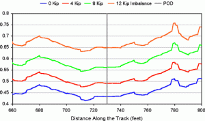
Tests indicate that predicted L/V ratios consistently increase as the air spring load imbalance increases. Figure 1 shows predicted single wheel L/V ratios at the derailing wheel for the four cases. (The distance axis is relative to the track geometry reference point.) The worst-case for the 12-kip imbalance produces an L/V ratio of 0.75 or greater.
Since the critical single wheel L/V ratio for a wheel with a 70-degree flange angle and wheel/rail coefficient of friction (COF) of 0.4 is 1.12, the peak value in this case does not indicate a significant derailment risk. The maximum predicted value occurs about 50 feet beyond the observed point of derailment (POD). One explanation for this is that the track geometry data available was limited to gauge and crosslevel measurements at 15.5-foot intervals. Alignment data were available in the form of stringline measurements only.
Effect of Varying Truck Turning Resistance
Investigators also looked into the role of side bearing conditions and truck turning resistance in the actual derailment. Figure 2 shows predicted single wheel L/V ratios at the critical trailing truck wheel as a function of the side bearing COF. The results are shown for the nominal case (no air spring load imbalance beyond that due to car weight distribution).
The maximum L/V ratios are predicted for the lowest friction value. That is, an increase in side bearing COF lowers the predicted L/V ratio. This is easily explained. At the leading truck of a vehicle, the direction of truck rotation and the resulting turning moment increase the lateral force at the truck leading axle high rail wheel. At the trailing truck, the direction of truck rotation and resulting turning moment are opposite to the leading truck. As a result, the turning moment tends to reduce the lateral force at the leading axle, high rail wheel. The lower the turning moment, the lower the beneficial effect, and the greater the potential for derailment of the leading axle.
For vehicles where a portion of the car weight is carried by the side bearings, the effect of the side bearing COF is important. For a trailing truck, an increase in side bearing COF reduces the predicted L/V ratio, while for a leading truck, the effect is the opposite. Under normal operating condition, the L/V ratios obtained are not significant. A seized side bearing, however, may create a significant increase in truck turning moment.
Effects of Wheel/Rail Friction
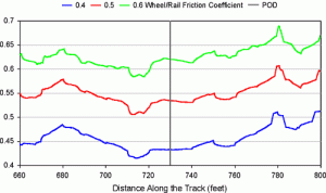
Yet another influence in the actual derailment was the potential effect of wheel/rail friction. Field observations indicated dry wheel/rail conditions. A high COF increases the lateral wheel forces while reducing the critical L/V ratio. As indicated earlier, a wheel with a 70-degree flange angle and a COF of 0.4 generates an L/V ratio of 1.12. The same wheel with a COF of 0.6 reduces the critical L/V ratio to 0.81.
Figure 3 shows predicted single wheel L/V ratios for the derailing wheel. These are again results for the nominal case (no air spring load imbalance beyond that due to car weight distribution). As expected, values consistently increase as the COF increases. The worst case produces an L/V ration of less than 0.7 with a COF of 0.6.
Results with Combined Effects
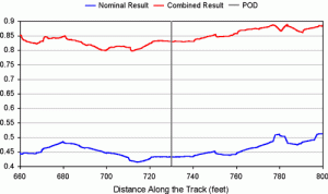
Since the actual derailment was caused by multiple factors, the final simulation examined a combination of effects, including an air spring load imbalance of 8 kips, a side bearing COF of 0.1, and a wheel/rail COF of 0.6.
Figure 4 compares predicted single wheel L/V ratios at the derailing wheel for the nominal and combined case. The predicted L/V ratio for combination of factors is approximately 0.8 to 0.9. Since 0.81 represents the critical single wheel L/V ratio (with a COF of 0.6), the predicted values imply a substantial risk of derailment. And since the L/V ratios for the derailing wheel are consistently high, no specific track location could be expected to initiate the actual wheel climb.
Rather, simulations indicate that the primary factor leading to a wheel-climb derailment was an air spring load imbalance, particularly for high values of imbalance, i.e., those with pressure differences of 25 to 30 psi and higher. Table 1 compares worst-case L/V ratios at each wheel of the vehicle for a range of factors. The shaded cells show the worst-case L/V ratio for each case. In most instances, the critical location is the high rail wheel of the leading truck, leading axle. Air spring load imbalance is the sole input making the high rail wheel of the trailing truck, leading axle the critical location for derailment.
The actual air spring imbalance is caused by a combination of: the static imbalance occurring on level tangent truck (due to the car weight distribution), improper adjustment of the car leveling system, and track twist or superelevation. If the car comes to rest in a spiral, the car leveling system will attempt to compensate for the superelevation ramp. This will increase air spring pressure at the leading truck (high rail side) and trailing truck (low rail side), and reduce pressure at the leading truck (low rail side) and trailing truck (high rail side). Derailment then occurs in the body of the following curve. The worst case occurs when the imbalance created by improper adjustment of the leveling system and the effect created by the entry spiral are additive.
The principal effect of diagonal air spring load imbalance is that static vertical loads per truck side are no longer uniform. In that air spring stiffness is roughly proportional to air spring pressure, the car is supported on “stiff” springs at two diagonal corners, and “soft” springs at the opposing corners. Under dynamic conditions, this can lead to further reduction in vertical load at the lightly loaded corners and a potential increase in single wheel L/V ratios. Based on the simulation results, the effect of air spring imbalance begins to become important at approximately 25 to 30 psi differential pressure. Air spring load imbalance alone is seldom enough to lead to a wheel climb derailment. However, when combined with other factors, such as wheel/rail friction coefficient and flange geometry, and operational issues (such as stopping in a curve entry spiral and then proceeding at slow speed), air spring load imbalance will significantly increase the potential for wheel climb.

Radovan Sarunac is Lead Mechanical Engineer in the Washington, D.C., office of Booz Allen Hamilton; Peter Klauser is a Vehicle Dynamics – Engineering Consultant.


