Effects of Secondary Suspension Imbalance on Wheel-Climb Potential (Part 1 of 2)
By Radovan Sarunac and Peter Klauser • July, 2007
Low-speed wheel-climb derailments are certainly not a new phenomenon. Investigations into the likely causes have long since identified the primary factors. Sometimes, however, old lessons need to be relearned. While all aspects of wheel/rail interaction, which includes wheel/rail profiles, friction, track geometry, and vehicle suspension systems, must be considered (APTA RP-M-010-98 Recommended Practice for Derailment Investigation Reports provides a good guide), this two-part article examines an issue specific to modern rail transit cars. That is, the effect of wheel unloading due to air spring imbalance.
In this study, vehicle dynamic response and an actual derailment were modeled using a vehicle dynamics simulation (VAMPIRE®). The vehicle model was based on a detailed model of a car equipped with powered, two-axle articulated frame trucks. Typical worn wheel and rail profiles were used.
Studies have shown that the forward rolling motion of the wheelset, combined with a high lateral to vertical (L/V) wheel load ratio, can induce this type of derailment. Two-point contact between the wheel flange and rail gauge face may create an additional moment that can lift the flanging wheel.
For each low-speed derailment, the following information is typically gathered and analyzed:
— Train Data: train speed, leading or trailing, manual or ATC mode of operation, unusual stops, and suspension behavior.
— Vehicle Data: condition of primary and secondary suspension (inflated/deflated and each air spring pressure), wheel diameter, wheel out-of-roundness, wheel profile measurements (MiniProf®), flange condition and wheel hardness, wheel back-to-back spacing, truck tram, production tolerances of the carbody bolster and center pin, force required to rotate truck, truck equalization, coupler condition, and brake condition.
— Track Data: curve, spiral, tangent, dry or lubricated, high or low rail, track gauge, gauge variations, gauge-face wear, crosslevel, rail profile measurements (MiniProf®), type of ties (wood, concrete), type of fasteners.
Low-speed wheel-climb derailments are not usually the result of a single deviation or cause; they typically are caused by multiple factors. The most common include: dry wheel/rail conditions (high coefficient of friction (COF) between wheel and rail, high lateral forces), newly trued wheels (high COF between the wheel flange and rail gauge face), shallow wheel flange angle (low Nadal criterion), track perturbations, excessive gauge-face wear (conditions for two-point contact), absence of restraining rail or guard rail, and low vehicle speed or sudden change in vehicle speed. Air spring imbalance recently has been added to the list.
The effect of flange angle and coefficient of friction can be assessed by analyzing the wheel climb derailment safety limit. Nadal’s criterion (expressed as L/V = [tan (δ) – μ] / [1+μ tan (δ)]) was used in this study. (The impact of angle of attack was not considered). Nadal’s criterion is based on the ratio of lateral (L) and vertical (V) forces acting on the wheel and rail just prior to derailment.
Nadal’s criterion, which is generally conservative, is dependent only on the wheel flange’s maximum angle of contact with the rail (δ, relative to horizontal) and the amount of friction (μ) between them. The minimum single wheel L/V ratio that can sustain a wheel climb is the derailment limit criterion used to indicate the risk of single wheel-climb derailment. In other words, when the L/V ratio is greater than the right side of the above equation, wheel climb may occur. The forward rolling motion of the wheelset, combined with a high value of lateral to vertical wheel load (L/V ratio), will induce this type of derailment. These conditions typically last for a minimum of approximately 5 feet before a wheel-climb derailment will occur.
Flange Angle and Friction
In simple terms, a high coefficient of friction and low flange angle are a recipe for wheel-climb derailments. Increasing the flange angle alone can significantly increase the L/V threshold at which derailments are likely to occur. Assuming a constant COF of 0.5 (dry rail), the L/V ratio at which a derailment will occur increases with flange angle. For a 63-degree flange angle, the derailment limit L/V is 0.73; for a 65-degree flange angle, the derailment limit L/V is 0.79; for a 70-degree flange angle, the derailment limit L/V is 0.95; for a 72-degree flange angle, the derailment limit L/V is 1.01; for a 75-degree flange angle, the derailment limit L/V is 1.12.
A wheel profile with a flange angle of 72-75 degrees substantially increases the L/V wheel-climb derailment limit and improves safety even under extreme conditions. The standard freight car wheel profile required by the Association of American Railroads (AAR) has a nominal flange angle of 75 degrees. The draft APTA wheel standard proposes a flange angle of no less than 72 degrees.
The coefficient of friction between the top running surface of the rail and the wheel tread varies between 0.1 (with leaves, slurry of rust and water) and 0.6 (bone dry, newly ground surface on sunny days). Fortunately, the extreme conditions do not prevail; most of the time friction is in the range of 0.25 to 0.35, or at worst 0.5. Freshly trued wheels are more prone to derailment since the COF between the wheel flange and rail increases due to the rough wheel (tread and flange) surface. As an illustration, Nadal’s criterion for derailment (i.e., single wheel L/V ratio) for a 63-degree flange angle indicates that under “typical” friction conditions with a COF of 0.3, vehicles approach the derailment limit with an L/V ratio of 1.04. Under “dry” friction conditions with a COF of 0.5, vehicles approach the derailment limit with an L/V ratio of 0.73. APTA recommendations (RP-M-009-98) for new truck design suggest that a COF of 0.5 be used for L/V ratio calculations (Nadal’s criterion).
Lubrication and Friction Modifiers
Friction plays a pivotal role in wear and contact fatigue, steering, hunting, wheel squeal, skid-flats, wheel climb and low rail rollover derailments. Managing friction at the wheel/rail contact patch is the single most powerful method for providing safe and economical operation. While traditional wayside and vehicle-borne oil-based lubricants effectively reduce friction, field experience has shown that no matter how they are applied to the wheel flange or gauge face of the rail, they typically migrate to, and contaminate, the top running surface of the rail. Although top-of-rail lubrication has been shown to reduce lateral forces, rail wear, and energy consumption, uncontrolled contamination of the rail running surface with conventional lubricants adversely affects train traction and braking.
Friction at the wheel tread/top-of-rail interface is a function of pressure distribution and the creep condition (relative slip or slide). The most influential factor is the interface layer between the wheel and rail which typically consists of residual lubricants, wheel, rail and brake pad wear debris, environmental contaminants, and moisture. The only way to control this interface is to dispense a substance with a known and desired friction value, i.e., friction modifiers.
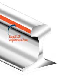
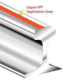
There are three primary types of friction modifiers. Low Coefficient of Friction (LCF) modifiers, with COF of 0.2 or less, are used to reduce friction at the wheel flange/rail gauge interface. High Positive Friction (HPF) modifiers, with COF of 0.2 – 0.35, are used at the wheel tread/top-of-rail to combat the growth of short pitch corrugation, reduce hunting or eliminate squeal (see Figures 1 and 2). Very High Positive Friction (VHPF) modifiers have the same friction range as HPF, but a “flatter” friction characteristic, with higher friction attained at lower creepage. Unlike grease and sand, the new-generation friction modifiers (which are generally applied in the stick or liquid form) do not migrate and tend to stay where they are applied and maintain the desired friction levels. Since lowering the COF between the wheel flange and the rail has the most significant positive effect on wheel-climb derailment protection, LCF modifiers should be used at critical locations.
Wheel and Rail Profiles
When a derailment occurs, wheels from the derailed truck should be measured with a profilometer, such as MiniProf®. Rail profiles of high and low rails should also be measured, prior to and after the point of derailment.
Analysis of worn wheel and rail profiles can determine the type of contact between the wheel flange root and rail gauge corner, and the wheel flange and rail gauge face. Two-point contact between the wheel flange and gauge face creates an additional moment acting as a lifting force on the climbing wheel. Gauge-face wear leads to “conformal” contact. The conformity between wheel and rail should be monitored and kept under prescribed limits. (An example of wheel/rail interface geometry for new and worn rail conditions is shown in Figure 3.)
Contact between the wheel flange and gauge face of the rail, i.e., “flanging,” typically occurs when there is either insufficient self-steering due to limited conicity of wheels or when steering capability has been exceeded. The effective conicity and COF of the interface play a key role in determining the steering (as well as stability) characteristics of the vehicle. This is especially important in curved track, where self-steering impacts wheel and rail wear. In the absence of lubrication, the COF between the wheel flange and rail gauge face is generally high (0.4 to 0.6). Wheel and rail wear, ride quality, generation of noise, and formation of corrugations are all directly influenced.
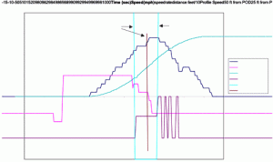
Modern rail vehicles are often equipped with a Vehicle Health Monitoring System (VHMS) capable of recording data, such as sudden changes and transitions from propulsion to coasting or brake modes. Post-derailment data required by the Federal Railroad Administration (FRA) may provide additional information regarding the vehicle speed and accelerations. Most wheel-climb derailments occur at low speeds. Sudden changes from propulsion to coasting or braking may affect the lateral friction between the wheel and top of the rail due to the accompanying change in longitudinal slip. Figure 4 presents an example of data captured by VHMS in close proximity to an actual point of derailment. The transition from accelerating to coasting then to braking is clearly visible.
Vehicle Leveling Systems
The secondary suspension of a modern rail vehicle consists of two air springs per truck and an independent damping system consisting of one lateral and two vertical hydraulic shock absorbers. The air spring provides the constant height of the carbody above the truck frame, regardless of passenger load. Secondary suspension height control is provided by leveling valves. For a four-point leveling system, this consists of two leveling valves per truck.
The car leveling system should not be confused with the load-weigh system. The load-weigh system latches the current load-weigh measurement when the car is at rest. The latched load-weigh value is based on the average air bag pressure on a per truck basis, and is used to compensate brake and traction effort for various passenger loads. Since the leveling system on one truck is independent of the system on the other truck, it is possible for the air springs on one truck to be set higher than those on the other truck. No adverse effect occurs, however, other than a threshold height difference and a small error in the signal given to the load-weigh system. This does not affect the wheel loads at each truck.
On a four-point leveling system, however, it is possible to have an imbalance in the air spring pressure between air springs of the same track. Such a pressure imbalance will cause a twist to the carbody, which will be resisted by an equal (but opposite) twist from the truck at the other end. This can result in a car that, while resting horizontal and appearing correctly leveled, has unequal vertical wheel loads.
Air spring imbalance also can be caused by end-to-end and side-to-side imbalances in car weight distribution. The higher the weight distribution imbalance, the greater the resulting air spring load imbalances. Weight distribution imbalance can be corrected by adding ballast at the appropriate locations. To minimize the operational costs associated with added weight, the imbalance requirements should meet those in IEC Standard 1133 (Rail Vehicle Traction).
IEC Standard 1133 specifies 60,000 in.-lbs. maximum for side-to-side imbalance. The end-to-end imbalance (measured at the trucks) should not exceed 2% of the vehicle’s ready-to-run (AW0) weight. Also, the effect of end-to-end imbalance should be verified with regard to the load-weigh system. Braking effort is based on the maximum of the front and rear truck load-weigh values, while tractive effort is based on the averaged load-weigh values. If adhesion demands exceed the available coefficient of friction, wheel spin or slide may occur. Analysis should be performed to confirm that the brake and the propulsion control systems can handle such imbalances in all circumstances (on wet and dry rail) without negative consequences.
![]()
Radovan Sarunac is Lead Mechanical Engineer in the Washington, D.C., office of Booz Allen Hamilton; Peter Klauser is an Illinois-based Vehicle Dynamics – Engineering Consultant.


