Understanding Stresses in Rails (Part 2 of 2)
By Jude Igwemezie, Ph.D., P.Eng • April, 2007
Part 1 of this article examined the contact and dynamic stresses generated by the wheel/rail contact loading environment. Part 2 examines the stress cycle at any point on the running surface of the rail as the wheel approaches it.
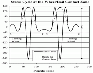
Stress in the railhead changes as the wheel traverses any point on the running surface. As the wheel approaches, the stress at point A (see Figure 1) is tensile, due to track uplift. At about 41 inches from this point, the stress reverses and becomes compressive. Both of these stresses arise from rail bending, alone. When the wheel is about 1/4 inch from this point, the stress reverses to become tensile, again, and exceeds the yield strength of the railhead material. When the wheel is directly over point A, the stress is reversed and becomes compressive, again, exceeding the yield strength of the railhead material. As the wheel passes point A, the stress cycle that was just described happens again, in reverse.
This means that the rail at point A will have undergone a three-stage stress cycle — ranging from tension-compression / tension-compression-tension (in which the yield strength of the railhead is exceeded) / compression-tension — under the action of one wheel (see Figure 2). One-quarter inch to the side of point A (beside the contact band), the stress value is less severe. Nevertheless, two reversing stress cycles shown with the dashed lines — tension-compression / tension (in which the yield strength of the railhead is exceeded) / compression-tension — are generated.
Residual Stress
Problems associated with internal stresses (also referred to as residual stresses), which are introduced during the making of rails, have been evident for the past two decades. The fact that few derailments have been attributed to them stems more from a lack of understanding of the phenomenon than from its absence in the cause of derailments. The primary interest in residual stresses, thus far, has been related to heat-affected zones, such as weld locations and areas within the railhead. Manufacturing and heat-treating processes that are used to produce head-hardened rail with improved properties (while maintaining geometrical tolerances) often produce residual stress in excess of acceptable values.
Rail manufacturers, today, are required to produce rail with a greater depth of hardness in the railhead, while maintaining a ductile web and base — all while keeping residual stresses low. This can be difficult to achieve, but it is essential in order to avoid residual stress-related rail failures and derailments. Research (1) into the manufacturing process and rail residual stress phenomena has shown that:
• Rail manufacturing processes control the residual stress pattern in the rail, but roller straightener settings can modify or completely alter these stress patterns.
• Roller straighteners can cause weakening of the rail web and fracture of the rail base. The damage is such that the toughness that would otherwise arise through the use of alloys is mitigated.
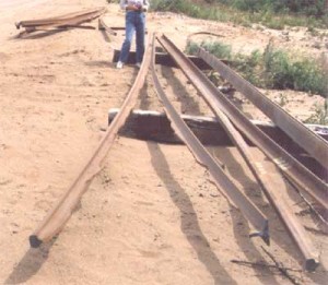
• Rails that contain stress intensities (due to residual stress) that are greater than the rail fracture toughness will fracture readily along the web (see Figure 3), whereas rails with residual stress intensities that are less than the rail fracture toughness will not readily allow catastrophic crack propagation.
• Stresses that can cause rail to fail catastrophically are located in the rail head and base; they have a longitudinal orientation.
• A plastic zone of up to 5 millimeters in depth is formed in the railhead during roller straightening.
• As the rail wears, the danger of catastrophic failure from residual stresses is reduced.
• Work hardening of material in the railhead redistributes the residual stresses, generating lower stress intensities within the rail web.
The development of standards, tests and quality control methods to control residual stresses in rails has led to improved specifications.
Thermal Stresses
Thermal stresses are generated by the difference between the ambient temperature and the rail laying temperature. Stresses that arise from uniform temperature change are considered axial. They heat or cool the rail uniformly. Stresses that arise from temperature variations in the rail (as the sun heats one side of the rail, then the other) can cause rail lateral bending. When combined with wheel loads, thermal stresses can be high enough to cause a pull-apart rail fracture. In some instances, such as during cold snaps, thermal stresses, alone, can cause a rail pull-apart. Figure 4 shows the thermal force generated in different rails as a result of temperature change from the neutral (rail laying) temperature.
Rail defects that result from fatigue or originate at inclusions can propagate under cyclic loading from trains. These types of defects, in combination with residual, thermal and dynamic stresses, can cause brittle fracturing of rails. Rail fracture requires an energy input, which is typically delivered by defective wheels or a rapid temperature change (cold snap). In North America, rail fractures predominately occur during cold snaps at the beginning of the winter months when tensile stresses approach one-half of the yield stress of the rail.
The Association of American Railroads (AAR) incorporated standards for acceptable sizes of wheel defects in Interchange Rule No. 41. These standards are based on the geometric size and nature of the defect on the running surface of the wheel. There are, however, an infinite number of possible wheel defects, which change in size and shape as the train rolls along. The magnitude and duration of the impact load resulting from these wheel defects is speed-dependent. Within recent years, an extensive network of Wheel Impact Load Detectors has been used by the major freight (and passenger) railways to identify wheels that generate high-impact loads.
Research into rail fracture resistance (2) and work to define the critical dynamic fracture load as a function of rail fracture toughness; defect size, location and orientation; rail ambient temperature; and residual stresses determined that:
• Defects such as vertical split heads, pipe web, head/web separations and horizontal split heads do not readily cause rail to fracture under impact loads. (This is due to a lack of crack opening forces.)
• Railhead transverse or detail-type defects, resulting from improper wheel/rail profiles and contact, readily produce rail fracture.
• Under impact load, a stiffer and heavier rail will attract a higher percentage of the dynamic loading, but will not fracture more or less readily than a smaller and flexible rail (3).
• The location, size and orientation of the defect, as well as tensile (thermal) forces and residual stress, are critical parameters in determining the rail fracture load. When a defect reaches a critical size, it will cause a pull-apart under tensile thermal stresses — regardless of whether the rail is new or worn.
Rail wear is a result of friction and stresses generated by wheel/rail contact. In tangent track, wear is produced by tractions, friction and vehicle hunting. On the high rail in curves, wear is produced by traction, creepage and flange forces. On the low-rail, wear is produced by lateral friction and traction and spin creepage from the wheels. Wear can be reduced with proper lubrication on curves and maintenance of gauge to reduce hunting.
Rail profile grinding generates “artificial” wear in which rail surface material that has plastically deformed and developed micro-cracks is removed. Rail grinding also controls the formation of transverse defects or contact fatigue damage.
Rail Stresses and Head Wear
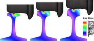
As Part 1 of this article shows, the stresses in rails are concentrated in the area of the applied load (as shown in Figure 1). Figure 5 illustrates how stresses in the low rail of a curve vary with head wear under load. As illustrated, stresses are concentrated in the railhead; the stresses across the rest of the rail section, where bending stresses dominate, are minimal. In the example with most wear (extreme left), the “green” band has traversed the thickness of the head of the rail. At this level of wear, the stresses would be expected to lead to the formation of vertical splits in the railhead. The angled “purple” band running from the top left to bottom right of each contour in this illustration is the neutral axis under the combined loading.
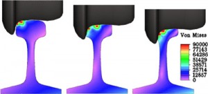
Similarly, the variation of stress in the high rail with wear under combined loading is shown in Figure 6. Again, the stresses in the head of the rail change with head wear, but the rest of the rail section, where bending stresses dominate, is not affected. Contrary to expectations, there is not a significant change in the bending stresses at the base of the rail. The angled “purple” band running from the top right to the bottom left of each contour in this illustration is the neutral axis under the combined loading. Figures 5 and 6 show that the dominant stresses in rail under wheel loading is much more dependent on the amount of material left in the head of the rail than on the amount in the gross section of the rail.
Rail Wear Limits
The information provided in Parts 1 and 2 of this article, thus far, is merely a means to an end. That end is the rail wear limit — the point at which the useful life of the rail is exhausted. In heavy-haul operations, the rails are used with tie spacings between 19 and 24 inches. At these spacings, most rail sections behave more like deep beams than like beams under flexure (bending). As a result, contact stresses govern what happens to the rail. The response of the rail to the wheel loads depends to a large extent on the reaction provided by the supporting ties, ballast and subgrade. This complex interaction produces wear on the top of both rails, as well as on the gauge face of the high rail.
The rate of rail wear is also dependent on the strength of the rail and its response to wheel loads. Field testing must be done on curves of varying degrees in order to determine rail rotation, the wheel/rail contact point, flange forces, vertical and lateral forces, and the effect of lubrication on rail movement and stresses in order to effectively establish wear limits.
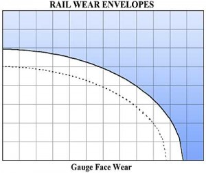
Using the information gathered from the field, structural analysis of the track system must then be performed to evaluate the stresses in different rail sections at various stages of wear. From the results of the stress analysis, wear envelopes (see Figure 7) are developed for premium and standard carbon rails. Each graph reflects the loading to the rail and the strength of the rail head material. Wear limits will be different from railroad to railroad because of differences in rail types, tie and fastening systems, maintenance practices, wheel loadings and even operating procedures.
Stresses in rails are very complex. Axle loads, vehicle behavior, track conditions, rail profiles and residual and thermal stresses in the rail all play a role. But contact stresses dominate all other stresses, and often represent the initiation point of contact fatigue damage to the rail. This is exacerbated by the passage of each wheel, which creates several stress cycles that add to the cumulative fatigue damage that is done to the rail. The magnitude of these stresses is dependent on the track system, wheel/rail contact, top-of-rail friction and the thickness of material left in the head of the rail. But no matter how you slice it, the rail investment cannot be properly managed without understanding its stress environment.
![]()
Dr. Jude Igwemezie is President of Applied Rail Research Technologies
(ARRT), Inc.
References
(1) Igwemezie, J.O., Kenney, S.L., and Gore, N.R., “Residual Stresses and Catastrophic Rail Failure,” proceedings of the 5th International Heavy Haul Conference. Beijing, China. June 1993.
(2) Igwemezie, J.O., Kennedy, S.L., Feng, X., and Rowan, W., “Defective Rail Fracture Under Dynamic, Thermal and Residual Stresses,” proceedings of the 5th International Heavy Haul Conference. Beijing, China. June 1993.
(3) Igwemezie, J.O., Kennedy, S.L., and Ca1, Z., “Dynamic Calibration of Track and Fracture Toughness Testing of Whole Rail Sections in Cold Temperature,” Track Structures Research II Task 2 Report, CIGGT Report No. 91.


