Drilling Down to Top-of-Rail Friction Control
by Bob Tuzik February 1, 2005
There are two primary approaches to friction management on rail transit systems: onboard and wayside. The most effective method depends upon the demands of the system. A relatively small system with consistent degrees of curvature, for example, might lend itself to onboard application. A system with localized, site-specific problems, such as tight radius curves, may be better served by wayside treatment. Embedded track systems or areas with pedestrian traffic in which contamination is unacceptable may benefit from an alternate approach in which a small amount of lubricant or friction modifier is pumped to the surface through a hole drilled into the head of the rail.
Research into the potential benefit of a drilled-hole approach to friction control was performed by the Transportation Technology Center, Inc., through the Transit Cooperative Research Program, an initiative funded through the Federal Transit Administration to leverage results from other segments of the industry.
Top-of-rail friction modifiers have been shown to effectively control friction and reduce noise in transit applications. Wayside gauge-face lubricators have been shown to reduce rail wear. Drilled-hole applications in some cases can be used to control friction at both the gauge face and top of rail. The drilled-hole system is designed to apply a very small amount of lubricant at site-specific locations. Initially designed and intended for paved track applications in which the use of typical wayside applicators is not feasible, the drilled-hole system requires a very small footprint. This is especially beneficial in that only a small section of the roadway must be disturbed in post-construction installations, Richard Reiff, Principle Engineer at the Transportation Technology Center, Inc., told delegates at Interface Journal and Advanced Rail Management’s Rail Transit ’04 Wheel/Rail Interaction Seminar.
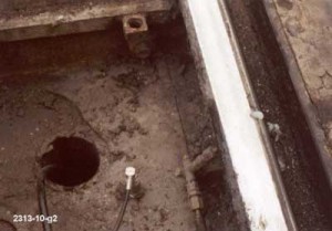
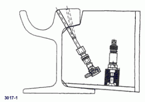
The Portland, Ore., Tri-Met system, for example, uses an SRS pump and activation system that is housed beneath a cover plate in the street (see Figure 1 on previous page). A vibration sensor activates the pump and the lubricant is pumped through a 3/16-inch-diameter hole drilled into the rail at a 70-degree angle to the gauge face (see Figure 2). The location of the hole through which the lubricant or friction modifier is applied can be angled more toward the top of rail to provide better top-of-rail coverage, or toward the gauge corner for better gauge-face lubrication. “Provided the output is properly controlled, there’s very little waste,” Reiff said. This is particularly attractive in public areas with foot traffic.
Also attractive is that the likelihood of over-application of grease or friction modifier is minimized. Significantly less lubricant is applied for every wheel pass when compared to traditional wayside applicators. This also means, however, that each applicator is able to cover a smaller area—one or two curves, at most.
One of the drawbacks to the system is that the applicator can’t easily be moved “Once you drill a hole in the rail, it’s fixed,” Reiff said. There’s little in the way of adjustment that can be done. “If the location is not right, if it’s too high or too low, a new hole must be drilled.” And while transit systems don’t change rails as often as freight railroads must, when rail is renewed, a new hole must be drilled.
While most of the Tri-Met applications are in embedded track, an open track site that better accommodated a hand tribometer was used for the tests. Microphones were located outside each track and between them. Four lubricants (three greases and one quasi-friction modifier) were tested over a two-week period. Effectiveness was measured at two carry distances, 200 feet and 1,200 feet from the applicators, which were located near the entrance to 8-degree and 8-degree reverse curves.
Depending on the lubricant, friction levels attained a steady state of about 0.3 at the gauge face and about 0.35 at the top of the rail after 50 – 120 axle passes in the 200-foot zone and 85 – 180 axle passes in the 1,200-foot zone. Effectiveness dropped off significantly beyond 1,500 feet from the applicator.
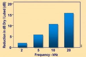
Noise reductions of about 15 decibels (dB) on average were measured at 200 feet from the applicator; reductions of about 10 dB were measured at 1,200 feet from the applicator. A comparison of noise reductions at various frequencies between dry and steady-state lubricated conditions indicates that noise levels dropped 3 – 5 dB at 2,000 hertz (kHz), 6 dB at 5,000 kHz, 10 dB at 10,000 kHz, and about 20 dB at 15,000 kHz (see Figure 3).
While track-maintenance personnel tend to balk at drilling a hole in the head of the rail, fatigue does not appear to be an issue. Finite Element Analysis was conducted, using a worst-case, hypothetical 20,000-pound wheel load (typical wheel loads on the Tri-Met system are about 14,000 pounds). With no hole in the rail, this wheel load would generate a 6,100-psi contact stress. With a hole in the rail, the wheel load would generate a 21,000-pound load. An arbitrarily doubling of the load to account for a dynamic factor generates about 42,000 psi at the hole. Since the fatigue strength of the rail steel is about 74,000 psi, these applications appear to be well below the danger level on tangent track where there is no lateral loading. Adding a 14,000-pound lateral load to simulate a curve, however, pushes the rail steel near its yield strength at the hole. So, Reiff said, it is important to understand that the installed location of this type of system is significantly limited to installations in tangent track without hunting-induced lateral loading.
![]()
This article is based on “Alternative Application System for Lubricating Street/Embedded Track in the Transit Environment,” a presentation by Richard Reiff, Principle Engineer at the Transportation Technology Center, Inc., at Interface Journal and Advanced Rail Management’s Rail Transit ’04 Wheel/Rail Interaction Seminar.


