The Basics of Successful Grinding (Part 2 of 2)
By Norman Hooper • July 2010
See Part 1.
Experience has shown that an efficient and cost-effective rail grinding program requires attention to basic track inspection and maintenance procedures. This includes attention to “hot spots,” such as joints, welds and road crossings.
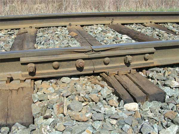
Figure 1 shows a rail joint at the end of its life. Note the broken joint bar, crushed ties, battered joint and broken tie plate. These conditions generate significant dynamic impact to traction motors and roller bearings.
Regulation for the inspection of joints in CWR is aimed at finding loose bolts and broken joint bars. In addition to finding loose or broken bars, maintenance personnel should try to determine what caused them. Are the rail fasteners in place? Are the joint bolts the right size and properly torqued? A mixture of 7/8- and 1-inch bolts when the standard is 1-1/8-inch is an invitation to a 10-mph slow order (or worse) when the bolts loosen or fail. While there’s no safety regulation compelling the use of a 6-hole bar in CWR with all of the right bolts installed to the correct torque, it’s good practice to ensure long life for the joint.
Equally important is ensuring that there is proper drainage and support at rail joints. A series of joints (temporary or otherwise) that are too close together is an invitation to poor surface and a rough ride.
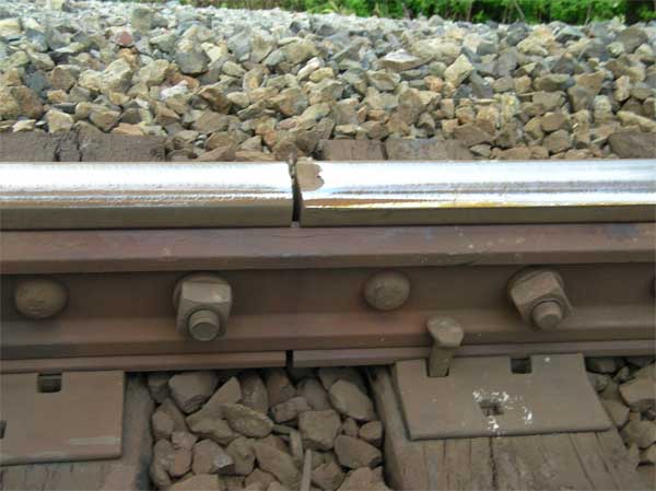
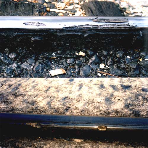
A joint in track will start to develop rail flow between the two rails. The amount of rail flow increases, and some surface cracking starts. The flowed rail material is brittle and poorly supported and it begins to crack out. As the flow advances and increases over time, small chips begin to break out (see Figure 2). The surface discontinuity imparts a dynamic load into the joint structure. Eventually, larger pieces of the rail head break out.
As the ends of the rails are battered, the uneven rail surface causes a dynamic load that destroys the ties and ballast below. As rail end batter increases, secondary batter forms along the rail due to dynamic load response from vehicle suspensions. This results in a weak spot in the track structure and a failed joint, with loose or missing bolts, or a broken bar (see Figure 3). The problem can’t be fixed by rail grinding; it needs basic timely joint maintenance. Slotting, an almost a forgotten art in CWR territories and on most shortlines, is a very effective method of joint maintenance.
If joints must be left in CWR territory, railways should use good ties, proper bars/bolts and slot the rail flow. Grinding cannot solve the batter and secondary batter issues of joints; it takes basic maintenance.
Weld Dipping
Weld dipping in CWR creates many of the same issues as rail flow. Good sub-support and regular grinding (approximately 0.004 inches of regular metal removal, while the growth is slow) is the solution. Weld dipping follows an exponential growth pattern; mild dips increase in depth at a greater and greater rate, and batter grows longitudinally from the weld. The depth of batter (weld dip) on thermite welds is often such that grinding is not a viable, cost-effective option, and a plug must be installed. Secondary batter also can occur in a dip over a shop flash-butt weld. Secondary batter will grow more quickly at dip areas with poor tie support. If weld dipping is not addressed by regular grinding, the batter grows, ties deteriorate and cause secondary batter on the rail surface.
Road Crossings
Maintenance grinding is also required at road crossings. Generally, rail wear in crossings is two to three times the rate of wear in the adjacent rails. Road vehicles pick up the lubrication or contamination that’s on the rails and increase the local friction, corrosion and wear rate. In heavy haul, softer older standard carbon rails will not stand-up, which is why active road crossings should have premium rails installed. Many crossing also have tie-quality and drainage issues that reduce rail support. Most crossings are not regularly ground for profile or rolling contact fatigue (RCF) because of the restriction of the pavement or mudrail.
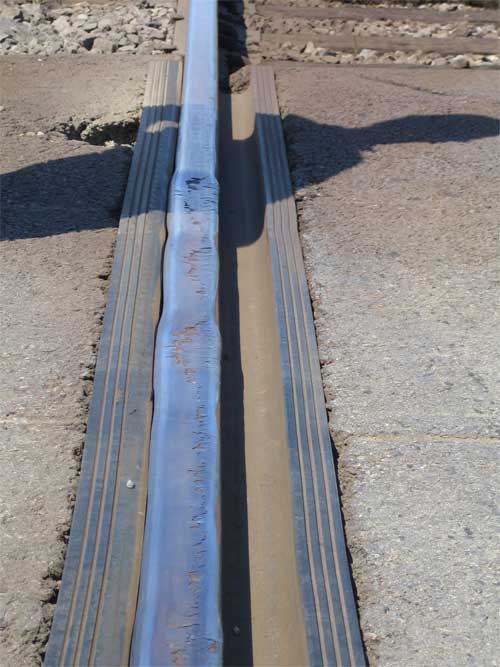
As a result, RCF takes a toll at crossings. Figure 4 shows a crossing in 45-mgt territory with a predominance of 286K unit coal trains. The rail is older, 265/270 Brinell hardness (Bhn) that was rolled in the mid ‘80s. It is referred to as “Tootsie Rail” — a hard outside (work hardened surface) with a soft center. Sectioning did not reveal any internal defects in the head area; the steel is just too soft/weak to withstand the dynamic loading. Timely grinding would have delayed the failure.
A “best practice” to achieve the most from a rail grinding budget and the lowest life cycle cost of rail is to use current technology to determine grinding locations and profiles. Excellent measurement and analysis tools are available that can be used to cost/benefit justify additional resources.
Profile Measurement
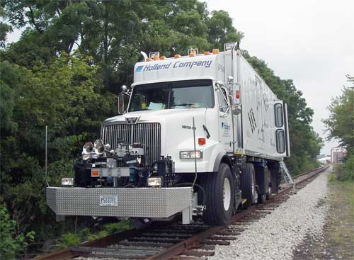
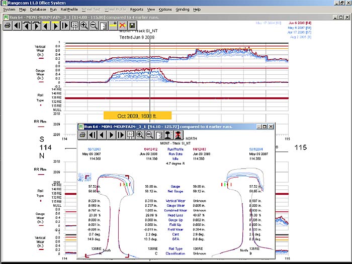
Rail profile measurement systems can be mounted on geometry cars, small stand-alone hi-rail vehicles or integrated with larger hi-rail systems that have gauge restraint measuring systems (see Figure 5). Rail wear, rail flaw, track gauge and surface measurements can be integrated with a railway’s maintenance records and made available to track personnel. An under-utilized strength of these systems is their ability to forecast maintenance and capital requirements. Figure 6 shows a typical output indicating rates of change of rail wear, track gauge and rail cant.
The railway industry isn’t about technology, it’s all about money: capital and operating costs. Rail measurement systems provide information on current conditions and also show the rate of change from previous tests. Trends can be analyzed to determine optimum maintenance points and long-term capital requirements. Integrated systems can calculate the long-term lifecycle costs of track assets and provide information on depreciation (a non-cash component of operating ratio). They can also deliver present value cost/benefit on the use of lubricants/friction modifiers, grinding, defect detection, premium rail and fasteners, increased tonnage or axle load, etc.
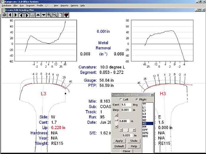
Rail measuring systems have sufficient accuracy to be used for rail grinding both in profile selection and material removal calculation. These measurements bear directly on grinding contractor productivity and the unit cost of production. They are vital for quality control and location history. Figure 7 shows a typical output for rail grinding profile selection and optimum metal removal.
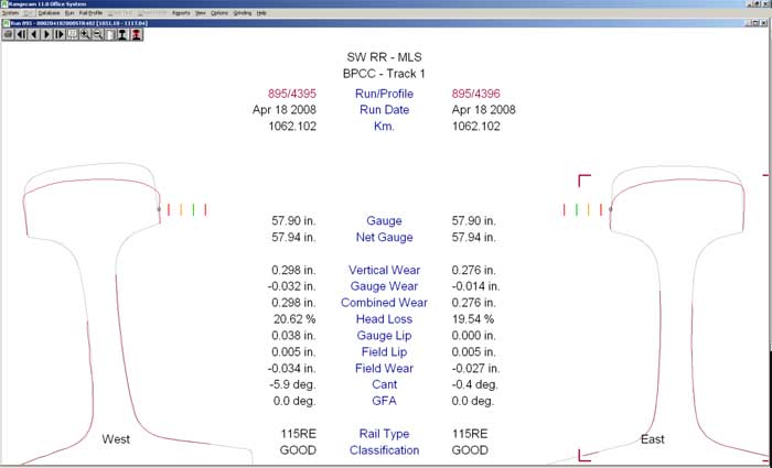
Effective as it is, rail grinding cannot correct or compensate for conditions such as wide gauge, which can have a combination of sources. Figure 8 shows a track where the low rail is severely canted to the field side. In this case, 1 in. of the 1-1/2 in. of wide gauge is due to rail cant. The grinding software will suggest a profile but this rail should not be ground until re-set.
Rail grinding will not economically compensate for excessive RCF or corrugation. The deterioration has to be caught in time. Serious effort should be spent on identifying areas where corrugation and RCF have started to form, and to develop a preventative grinding program. Left unchecked, impact loads from corrugation cause damage to roller bearings, traction motors, ballast and ties (concrete, in particular), and can result in early rail removal.
Corrugation can also rapidly re-establish despite expensive multi-pass corrective grinding because the grind rarely gets deep enough into the parent metal. If preventive grinding is deferred, corrective grinding will be required at a significantly higher cost.
Work has been done to correlate surface crack length with defect development (1). Rail hardness, steel cleanliness and residual stresses each have an effect on the likelihood of defect development. Some rails with extensive surfacing cracking and shelling will not develop transverse defects (TDs). But wherever rail (type/manufacturer/year) has been shown to develop TDs from gauge-corner RCF, crack lengths should be measured and recorded during inspection. The data should be analyzed to predict future defects and to determine optimum grinding cycles.
Another issue related to surface cracking is that the stress at the crack tip is increased enormously when a “incompressible” liquid such as water from rain or snow or a lubricant is trapped at the end of a crack and compressed by a passing wheel set. This will cause surface shelling and flaking (see Figure 9).
Areas around rail lubricators are particularly prone to this. A good practice is to ensure that areas around lubricators are prepared for the grind cycle, rather than being skipped over.
Preventive rail grinding in combination with lubrication can dramatically increase rail life (2). They must be combined because lubrication, alone, prevents the normal wear and removal of damaged surface material. Where a rail has well-developed surface cracks, liquid lubricants infiltrate the crack, reduce friction between the crack faces and accelerate crack propagation. The application of lubricants to damaged rail can increase the rate of crack growth.
Overall, an effective rail grinding program requires a comprehensive inspection/maintenance program. It requires inspectors to:
• Monitor tie and surface conditions.
• Utilize technology to obtain the lowest life-cycle cost of assets. Data can be used to make a case to management to support grinding and lubrication programs.
• Improve track and walking inspections.
• Inspect and perform maintenance at hot spots. The problems can’t all be found from a hi-rail vehicle traveling at 30 mph.
• Adopt effective preventive grinding and lubrication/friction modification programs to substantially increase rail life.
A simple summary is this: grinding maintains, lubrication sustains.
References
(1) Grassie, S., “Rolling contact fatigue on the British railway system. Treatment of rolling contact fatigue in rails: a guide to current understanding and practice,” RT/PWG/001 issue 1, Railtrack plc, London, February 2001.
(2) Eadie, D., Vidler, B., Hooper, N., Makowsky, T., “BC Rail Top of Rail Friction Control: Lateral Force And Rail Wear Reduction In A Freight Application,” International Heavy Haul Association Conference 2003.

