Specialized Rail Profile Grinding on MBTA
by Bob Tuzik • April 10, 2005
Rail Grinding has been used to solve a host of problems on transit systems. It recently was used in Boston to remove a new wrinkle. A specialized grinding program was initiated in 2002 on the heels of a series of light-rail derailments on the Massachusetts Bay Transportation Authority (MBTA) Green Line that occurred in the summer of 2000.
An initial study indicated that the 63-degree wheel flange angle on the cars was not sufficient to prevent derailments. As a result, the MBTA adopted a new Interim Wheel Profile (IWP) with a 75-degree flange with a 1:20 taper to replace the 63-degree wheel flange with a 1:40 taper that had been used.
Introducing the new flange angle was only the first step in the MBTA’s plan to reduce derailment potential, extend wheel and rail wear life and improve wheel/rail interaction on the system. The new 75-degree flange angle raised Nadal’s (L/V) limit by 50%, which permitted higher lateral forces, but the flange angle deteriorated rapidly and was difficult and costly to maintain.
While most transit properties establish their re-truing cycles based on mileage and flange thickness, MBTA’s cycles were based on a more elusive change in the flange angle. A 72-degree maintenance limit (later relaxed to 68 degrees for the wheels with solid axles and 72 degrees for the center, low-floor independently rotating wheels) was established for the cars. Based on these limits, wheels required re-profiling every 3,000 miles and were condemned for diameter by 20,000 miles.
“We weren’t wearing the flanges thin,” says Joseph Oriolo, MBTA’s Senior Project Manager – Maintenance-of-Way. “We were cutting the wheels because of the change in flange angle.”
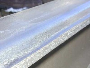
In addition to the issues relating to flange angle, wheels on the MBTA have a shallow, 3/4-inch flange length. As the wheel flanges contacted the gauge face of the rail, they wore the upper portion of the rail and created a shelf beneath the tip of the flange (see Figure 1). The shelf became an area of concern. Depending on the diameter of the wheel relative to the length of the flange, flange bearing could occur.
“We had to find a way to remove that shelf or replace the rail,” Oriolo said.
Rail replacement was considered but was rejected as too costly. MBTA concluded that it had to find a cost-effective way to grind away the shelf that had been carved into the rail, then grind a 10- to 20-degree angle on the gauge-face that would be compatible with the 75-degree IWP. The problem was, grinding at those angles had never been done in North America.
High-Angle Grinding
In order to remove the shelf that the wheel flanges had cut and to grind the appropriate angle on the gauge face of the rail, the rail grinder would have to be able to position grinding motors to grind at 75 degrees or greater. Up to that point, production grinders were capable of grinding at a maximum 45 – 50 degrees. While switch grinders were capable of grinding at steeper angles, none were capable of operating within MBTA’s clearance envelope or on the system’s tight-radius curves.
“Not only did we have to grind at an impossible angle, but we had to figure out how to do it productively,” Oriolo said.
The MBTA hired Advanced Rail Management to come up with a solution. ARM worked closely with its subcontractor, Loram Maintenance of Way, to design a program to meet the MBTA’s needs.
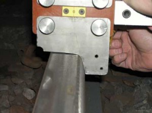
“Our goal was to grind as near vertical as possible on the gauge face of the rail,” says ARM President Gordon Bachinsky. “We could see that a 10- to 15-degree gauge-face angle would mate well with a 75-degree flange angle on the wheel.” (See Figure 2.)
Loram modified two of its L-Series grinders, which feature four 30-hp motors (two per rail) on each grinding cart, to
perform the task. It adopted the use of grinding stones with a 1-inch wall (in place of 2-inch wall stones that are more commonly used) in order to remove the shelf that had been cut into the rail by the wheel flanges. But that wasn’t the only problem. Normally, the weight of the grinding motor provides much of the force required for grinding. But with the motors positioned at 80 degrees to remove the shelf and grind the gauge face of the rail, they couldn’t provide enough grinding force.
“We put springs on the modules to pull them inward and provide downward grinding pressure against the rail,” says Don Minge, manager of Loram’s Light Rail Division.
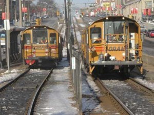
The initial effort to remove the shelf on the gauge face of the rail required 40 – 50 passes. Soon after the grinding work started a second grinding cart was added to provide 8 motors (four per rail), overall. In order to hasten the process, the MBTA for some period used two grinding units (see Figure 3), each with two grinding carts (with four motors per cart.)
Removing the shelf on the rail required constant attention. There were many wheels with the old 63-degree flange angles operating on the line until they could be turned to the new IWP. These wheels tended to re-cut the shelf that the grinder was eliminating and wear a high-degree angle on the gauge face of the rail. As more cars came on line with the new 75-degree IWP, less damage was done to the rail, but additional work was required to break the cyclical pattern of gauge-face degradation. Once all of the wheels operating on the B Segment (Commonwealth Avenue) of the Green Line were re-profiled to the IWP, ARM began profile grinding the running surface of the rail to promote vehicle steering and prevent wheel-flange/gauge-face contact.
Rail Profile Grinding
Working with its subcontractor RESCO Engineering, ARM designed a series of new rail profiles for curved track to promote steering in curves down to approx. 600-ft radius. ARM and RESCO also performed a pummeling analysis to design a series of profiles to promote better steering and correct the sinusoidal, side-to-side movement of the vehicles. The sinusoidal movement was exacerbated by tight flange clearance of 5/32 inches, versus a more standard clearance of 7/16 inches on heavy rail, which reduced the ability to generate rolling radius difference in curves. The existing flat and wide contact band that in some cases encompassed the full head of the rail provided evidence that the vehicles were unsteered.
“The wear pattern in tangent track was a lot like that of the high rail in curves,” Bachinsky says. A by-product of grinding off the shelf was a slight increase in flange clearance, which helped increase rolling radius difference.
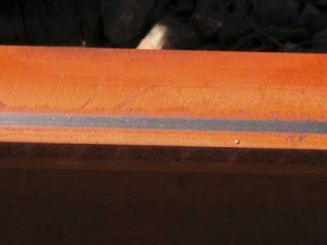
ARM/RESCO designed a series of new profiles with 3/8-inch running bands to take better advantage of rolling radius difference and thereby improve steering (see Figure 4). Multiple contact points reduced point loadings and the potential for rolling contact fatigue; the profiles also spread the wear to help maintain the tread shape and surface of the wheel.
“By varying the contact position in curves and in tangent track, through a well-designed grinding and profile strategy, we can produce a more effective wear pattern over the wheel profile,” RESCO President Roy Smith said. “This helps to prolong the life of the wheel profile.”
Other objectives of the new profiles were to:
• Avoid two-point contact situations as much as possible.
• Create sufficient rolling radius difference to promote steering and avoid anti-steering.
• Avoid excessive effective conicity.
• Avoid the development of extremely wide contact patch.
• Avoid sharp gauge corner radii and contact too near the gauge corner.
In the simplest sense, the best way to prevent the flange angle from degrading is to prevent contact with the gauge face. “If the flange doesn’t touch the rail, it can’t wear it and it can’t change it,” Oriolo says.
ARM developed a grinding map in which various profiles were used, depending on geometric configurations. With the new profile grinding strategy in place, vehicle steering has improved and gauge-corner flange contact virtually has been eliminated in all but 600-foot radius or tighter curves. (This applies only to steered wheels with traditional, solid-axle trucks. The Independently Rotating Wheels on the low-floor cars are not responsive to the steering forces that apply to conventional trucks.) With that, wheel flange wear has been reduced dramatically.
“We have now gone approximately 10,000 miles without needing to true a wheel,” Oriolo said. “Thus far, we’re seeing an approximate 300% increase in mileage between wheel truing cycles.”
Most satisfying, perhaps, is that with the IWP and the rail profile grinding program in place, new positive wheel and rail patterns are beginning to emerge. Formation of the shelf on the gauge-face of the rail has significantly reduced. When it reappears, it forms a steeper gauge face angle than previously observed. Instead of wearing shallow, wheel flanges are wearing to the steeper end of the range. “The flanges are going from 63 degrees up to 70 degrees in some cases,” Oriolo says.
MBTA is monitoring wheel flange angle wear diligently and recently installed WheelScan, a real-time wayside measurement system produced by KLD Labs Inc., that uses a combination of lasers and video cameras to capture wheel profiles on the system. The data will be integrated into ARM’s optical rail measurement database to analyze wheel/rail interaction.
“This has been a rewarding and real learning experience,” Oriolo said. “We started with a wheel/rail problem, but we needed the cooperation of all departments, car equipment, m/w, transportation—and our suppliers—to solve it.” There is still work to do, he says, “but we have made significant progress in optimizing our wheel/rail interface.”


