Practical Rail Grinding
by Fred Prahl, Eric Magel & Peter Sroba • April 4, 2005
Rail grinding, first developed as a technique for treating corrugations, has become an essential component of track maintenance for freight railroads and transit properties. During the 1960s, railroads began seeing rail corrugations developing to depths of about 0.080 to 0.120 inches (2 to 3 mm) on the low rails of standard carbon steels after 50 mgt; corrugation occasionally developed on the high rails, as well. In the early days of rail grinding, railroads ground a 2-inch-wide running band in the center of the rail head to remove corrugations. While this worked reasonably well, the grinding motors in early grinders were fixed in orientation. This type of grinding left the rail head flat. Rail life was extended, but plastic flow was not removed and cracks remained where the valleys of the corrugations had not been removed. Contact with the sharp reverse convex curvature of hollow-worn wheels remained, and the cause of corrugation formation was not effectively addressed.

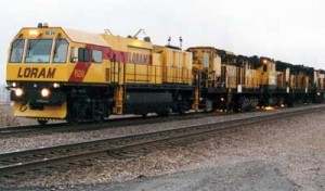
The modern rail grinder is a high-capacity, computer-controlled machine with the ability to grind at angles up to 70 degrees (in most cases) to the gauge side of the rail (see Figure 1). They are able to provide as much as 30 hp to each grinding motor and to apply various patterns to the rail by positioning the grinding motors at different angles. Rail grinding operators can precisely position the grinding motors and control individual power consumption with greater accuracy than ever before. The challenge facing railroads today is how to make the best use of the current grinding technology.
When it comes to rail grinding, the needs of one railroad can differ vastly from another. But for railroads in a preventive grinding mode, a relatively generic format can be followed. It includes:
• Forward single pass grinding as much as possible.
• Occasional (but infrequent) two or three passes to pick up curves that are particularly problematic.
• Optimization of rail profiles to minimize damage between intervals. These profiles may be specific to the territory.
• Optimization of patterns to make the most effective use of each grinding pass.
But even railroads with decades of grinding experience find that a formulaic approach only partially satisfies their needs. With increasing traffic density on many lines, railroads are struggling with the logistics of getting a rail grinder to demanding locations on cycle. Pressure to extend the grinding interval requires appropriate changes to the grinding process.
Designing a Practical Grinding Plan
Railroads grind primarily to control surface fatigue defects and to maintain rail profiles that significantly increase rail life, control corrugations, and improve train stability and curving. However, each property has unique characteristics, which vary from location to location. These variations drive rail profile design as well as the grinding strategy. It is more important to design a rail profile and grinding plan that is practically achievable than it is to design and apply a profile that might otherwise be “perfect” from a wheel/rail perspective.
Union Pacific, for example, struggles to maintain grinding cycles in its Red-X 400-mgt territory. As a result, UP and the National Research Council Canada’s Centre for Surface Transportation Technology (CSTT) developed new profiles to improve wheel/rail interaction and minimize the required grinding effort. Taking specific track features that included predominantly premium steel, mild curvatures (2.5 degrees or less), less than 1/4-inch wide gauge in curves, nominal 1/4-inch tight gauge in tangents, and minor cracking on the gauge corner of high rails and the gauge side of low rails into account, CSTT recommended new profiles for high rails in sharp curves, high rails in mild curves, low rails in all curves, and tangent track and curves less than 0.25 degrees. The profiles were designed to provide most of the benefits to be had from so-called “ideal profiles,” in terms of reduced contact fatigue and wear, without excessive metal removal. (If these site-specific profiles were applied to other UP divisions, the benefits would be less—perhaps 70% – 80% of that achievable with the ideal profiles.)
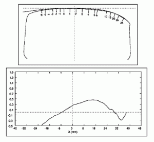
The profile for the high rail in sharp curves, for example, provides some gauge-corner relief to protect from the initiation of rolling contact fatigue and allows for the longer grinding intervals that are needed on this high-density line. The profile also provides for conformal contact on the gauge corner to improve steering. The low rail profile produces a 10-inch radius contact band biased to the field side of center to take the load off the spalled center band. With UP’s excellent control of gauge, little field-side relief was required on the low rails to protect the rail against false flanges on wheels. In tangent track, all contact is shifted to the field side to address hunting and tight gauge. This approach, combined with the central or gauge-biased contacts that exist outside the Red-X territory, is meant to spread wheel wear to reduce hollowing. Figure 2 shows a metal-removal plot for the recommended low rail profile.
Preventive Grinding
Work done by MRS Logistica in Brazil represents another example of a profile design strategy that makes a modest compromise on wheel/rail performance to improve the practicality of implementation. MRS is a broad gauge (63-inch) railroad serving Minas Gerais, Rio de Janeiro and São Paulo. The main products hauled are iron ore (68%), steel products, cement, bauxite, coal, agricultural products and containers. In 1998, rail on the Steel Line, one of the four MRS lines, exhibited evidence of corrugation, head checks, spalling, severe plastic flow, dipped welds, engine burns and detail fractures. In 1998, 132 service failures occurred in 217 miles (350 km) of track.
Loram Maintenance of Way and CSTT designed new rail profiles and developed a preventive grinding strategy tailored to MRS’s needs. As a result of the program, rail service failures have declined dramatically and the rail wear rate has been reduced nearly by half since 2002. (Fuel consumption also was reduced by 2% – 3%.) Consequently, MRS saved about $25 million in rail purchases over the past three years. A number of issues have arisen since the rail profiles were first designed and the grinding program began, however. These issues have had an impact on how effectively the profiles can be implemented in track and on the grinding interval required for staying ahead of rolling contact fatigue.
One problem is that traffic on the network has increased significantly since the profiles were designed and by 2007 is expected to be double what it was in 2001. This will make the original rail profiles obsolete unless the grinder can maintain the grinding interval established in 2001. The tonnage increase is in the form of more trains which reduces the track time available for grinding and creates difficulty in sticking to the desired grinding interval.
Another problem is that two of the designed rail profiles have proven difficult to implement due to their high metal-removal requirements, especially when grinding them into rails with a large crown radius. The intent of the two designs (one is a tangent profile, the other is for low rails) was to shift the contact towards the field side, particularly for the low rail profile. This would add a small positive increment to the maximum rolling radius difference in sharp curves and help ensure that contact was spread across as much of the wheel tread as possible. Interim steps have been initiated to meet the original profile objectives while reducing metal-removal requirements—a further attempt to emphasize practical achievability over installing the “perfect” profile. (See “Preventive-Gradual On-Cycle Grinding: A First for Brazil,” published in the proceedings of the 8th International Heavy Haul Association conference in June 2005.)
Despite the benefits proven in the past, rail maintenance managers struggle to justify, retain and manage rail grinding programs with limited budgets. Still, tests have shown that rail grinding can effectively extend the life of rail in track. As reported by P. Sroba and M. Roney in “Rail Grinding Best Practices” at the 2003 American Railway Engineering and Maintenance of Way Association’s annual conference, one North American Class 1 railroad compared no grinding, corrective grinding and preventive grinding strategies in test zones. Table 1 shows a significant increase in rail life with preventive grinding because rail was replaced due to wear instead of fatigue. This railroad continues to use test zones for refining its wheel/rail maintenance strategies by monitoring the interaction between different grinding strategies, gauge-face lubrication and top-of-rail friction management. The railroad recognizes that grinding and friction management are crucial to a healthy wheel/rail interface and adjusts both strategies to optimize the results.
Railroads embarking on a grinding program may not be able to adopt a preventive grinding strategy immediately. Often, the railroad will be struggling with a particular problem, such as corrugation, hunting, or broken rails from rolling contact fatigue. Once the immediate needs are addressed, however, a practical and achievable preventive grinding program that optimizes wheel/rail interaction will best serve the railway property’s best interest.

Fred Prahl, is Director – Sales and Marketing; Eric Magel is Senior Engineer; Peter Sroba is Principal Engineer, National Research Council Canada, Centre for Surface Transportation Technology.


