
Measuring and Designing Rate of Change in Track Alignment
by Jeff Tuzik

In order to solve a problem, you have to be able to measure it. And while there are generally no new problems in railroading, tools and techniques of measurement continue to evolve. Over the years, engineers at the Union Pacific Railroad have noticed a deficit in traditional methods of measuring track alignment. Based on case studies, field work, and hard-won experience, they’ve focused-in on measuring the rate of change in alignment over 31 feet. Their investigation includes curve spirals, connecting tracks, turnback curves, reverse curves, and turnouts. Experts from the Union Pacific presented their findings at the 2023 Wheel/Rail Interaction Heavy Haul Conference, and posed an open question to the room and to the industry on how best to further develop techniques to measure alignment.
Following some difficult-to-explain incidents at various locations on Union Pacific’s network, a team of in-house experts began looking deeper into the root-cause. They quickly zeroed-in on track-alignment deviation as the likely culprit.
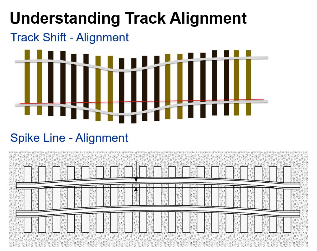
Within the industry there are effectively two types of alignment generally considered, said Mark Montoya, Manager of Track Maintenance & Engineering at the Union Pacific’s Southern Region. The first is track shift alignment wherein the entire track structure, the ties, the ballast — everything, moves. The second type is spike line alignment. This is a condition in which track alignment shifts in reference to the track structure — often (but not always) in such a way that causes a gauge change issue, as well. Track shift alignment issues can generally be fixed by a tamper coming through and correcting the issue, Montoya said, but the industry currently lacks the technology to automatically find and fix spike line alignment issues, he added.
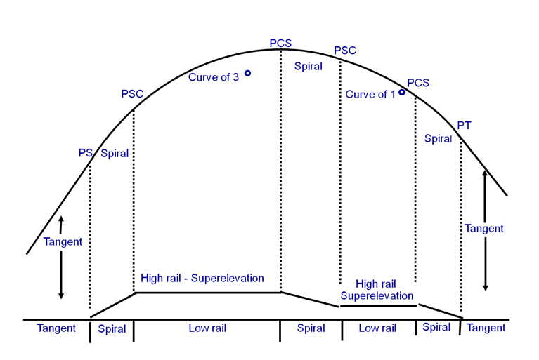
Alignment issues appear in both tangent track and in curves, although detecting them in curves is more difficult, sometimes significantly so. In the traditional geometry of a curve coming out of tangent track, a curve begins at the point of spiral (PS), transitions into the point of spiral in the curve (PSC), and then into the curve body. Between the PS and PSC, the track is also transitioning from level to full superelevation. Compound curves complicate matters by adding in a change in the degree of curvature and/or superelevation within the greater curve.
Inspectors must also bear in mind that an extreme rate of change in alignment over 31 feet can be an “engineered” track condition, i.e., one that is built-in during track installation and / or maintenance.
Under Federal Railway Administration (FRA) minimum safety standards (part 213.55) there are specific limitations on alignment deviation in curved and tangent track. In practice, and from a regulation standpoint, uniformity is measured over 248 ft, said Blake Smith, Compliance Manager on Union Pacific’s Southern Region. The FRA also gives clear guidance on how to measure curve alignment. These measurements are based on 62-foot cord measurements taken at multiple stations along the curve. But the FRA doesn’t specify a minimum spiral length concerning alignment uniformity, Smith said.
This becomes relevant in cases like compound curves and turnouts that may not be long enough for even a single 62-foot cord measurement, Smith said, creating a situation in which the ability to measure alignment against its uniformity requires an additional metric: the rate of change in alignment.
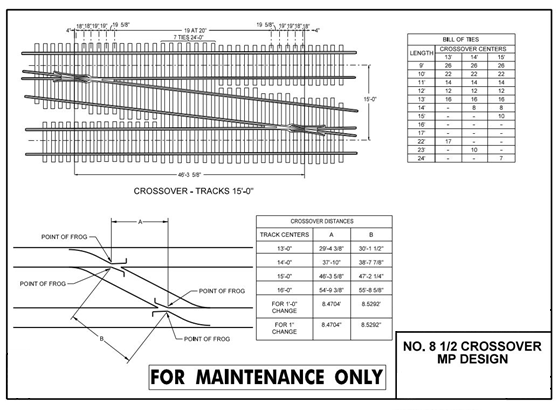
One such complicated piece of trackwork is Union Pacific’s No. 8 crossover. Based on the engineered design for this crossover, the longitudinal distance between the two frogs is roughly 45 feet, he said. This means that when a 62-foot-long car passes through, the distance between the trucks is longer than the distance between the frogs, leaving the car “straddling” two tracks. “A car by itself can negotiate the crossover, but add in the complications of cars on either end of that long car, and issues can arise,” Smith said. At a certain point, situations like these can generate lateral/vertical forces (L/Vs) that are high enough to cause a wheel-climb derailment. “The exact point of that threshold is part of what we’re trying to determine,” he said.
One site became a focal point for the development of a rate-of-change in alignment measurement methods and specifications. According to design specifications, this particular turnout was perfectly within spec, Union Pacific’s Mark Montoya said. Yet, after multiple incidents occurred at the site, the turnout was eventually replaced – again to specification. “We didn’t find the root-cause, so we didn’t solve the problem,” he said.
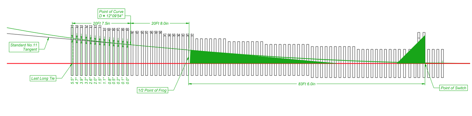
The engineering team then focused-in on the sharp curve coming out of the turnout — and the very high rate of change in alignment — as the culprit. The solution in this case was to model and then redesign the curve’s spike alignment — in fact taking it out of its theoretically ideal position. This proved to be the solution to the problem. “This goes against orthodoxy, manipulating the spike line behind the frog, but it was the right thing to do in this case,” Montoya said.
Part of the problem is that designs exist within Class 1 standards for some lower-speed turnouts that include a rate of change in alignment that would be deemed unacceptable if measured anywhere else, Blake Smith said. And when it comes to derailment risk, high rates of change in alignment can cause issues whether the condition is an actual defect or is part of the designed track.
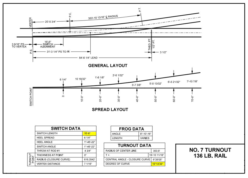
The No. 7 turnout is an example of this. Its design specifies roughly 16-degrees of curvature, which is effectively 16 inches of alignment deviation, he said. That 16 inches of change in alignment — from tangent track to a 16-degree curve — over 16.5 feet, is a design feature that is generally accepted in the industry, Smith said. But a 16-inch alignment deviation over 16.5 feet anywhere else, would be taken out of service. “This raises the question: Why are some conditions allowed in an “engineered” design, but not anywhere else?” Smith asked. This type of scenario also further confuses the issue of defining uniformity and deviation from it, he said.
These cases and others like it suggest the need for another way to measure rate of change in alignment, particularly for field inspectors. “We need measurables and thresholds,” Montoya said. Ideally, this should include criteria that inspectors can measure in the field to identify potential alignment issues that fall outside the normal operating environment. The ability to make such measurements could allow inspectors to detect locations that might be non-problematic most of the time, but represent a high derailment potential under a worst-case wheel/rail interaction scenario, he added.
While the standard methods for measuring alignment have served and continue to serve the industry well, it’s clear that there are outlier cases requiring additional finesse and engineering to navigate. These issues aren’t unique to any one railroad, and it therefore seems to be an issue ripe for industry collaboration; the development of a rate-of-change in alignment measurement techniques that can be used by field inspectors could save the industry significant time and effort.
“I think this needs to be a focus for track geometry design going forward,” Matt Dick, Chief of Strategy and Development at ENSCO Inc., added during a post-presentation discussion session.
And if “engineered” changes in the rate of change in alignment at some types of turnouts or other fixed points in track are here to stay, then, perhaps, changes to operating procedures should be made to accommodate and account for them.
“Rather than assessing the issue at derailment sites,” Montoya said. “I’d like to see the industry become proactive about this.”
But Union Pacific is not waiting for that to happen. It already has begun working with the Vehicle/Track Interaction Research program at Simon Fraser University in Vancouver, B.C., to compile data and perform simulations on expected L/Vs in certain situations to determine “how much is too much,” Blake Smith said. The project will help identify potential risks associated with how car types and various car-type combinations respond to a high rate of change in alignment and other track conditions in real-world situations.

Jeff Tuzik is Managing Editor of Interface Journal.
This article is based on a presentation made at the WRI 2023 Heavy Haul conference.