Testing Railway Vehicles to Improve Vehicle/Track Interaction
By Robert Masar • March, 2006
Significant increases in high-speed international traffic throughout Europe have led European railways to establish new comprehensive technical rules to ensure acceptable parameters for vehicle/track interaction. Current measuring systems and data collection and processing capabilities have made it possible to test and homologate new railway vehicles before they go into service, and to test existing vehicles when operating conditions change.
It is also necessary to ensure that the existing level of safety and reliability is not compromised when changes in design (such as new track conditions) or operating practices (such as the introduction of higher speeds), either of which may result in higher wheel/rail lateral or vertical forces, may occur.
In March 2005, The European Committee for Standardization and the Technical Committee for Railway Applications (CEN/TC 256) approved the European Standard EN 14343:2005: Railway applications – Testing for acceptance of running characteristics of railway vehicles – Testing of running behavior and stationary tests. EN 14343 provides a much-needed standardization for testing methods and acceptance thresholds which the following countries must implement: Austria, Belgium, Cyprus, Czech Republic, Denmark, Estonia, Finland, France, Germany, Greece, Hungary, Iceland, Ireland, Italy, Latvia, Lithuania, Luxembourg, Malta, Netherlands, Norway, Poland, Portugal, Slovakia, Slovenia, Spain, Sweden, Switzerland and the United Kingdom. The Standard applies principally to all vehicles used in public transport which operate without restriction on standard gauge tracks (1 435 mm).
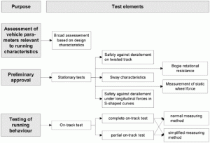
The testing of running characteristics is part of the type-testing of newly developed vehicles, or those that have had relevant design modifications, or changes in their operating regimes. Testing of vehicles’ running characteristics consists of preliminary approval tests (mainly stationary tests) and tests of running behavior (on-track tests).
Vehicle parameters relevant to running characteristics include: planned maximum permissible speed of the vehicle, planned permissible cant deficiency, the smallest curve radius to be negotiated, wheel arrangement, wheelbase and distance between bogie centers, center of gravity height, weight of the vehicle, wheel force and axle force distribution, unsprung mass, primary suspended mass, secondary suspended mass, moments of inertia of vehicle body (around z-axis), torsional stiffness of vehicle body, torsional stiffness of bogie frame, tractive effort, dimensions of wheel and wheelset, wheel profiles, characteristics of primary and secondary vertical suspension, characteristics of axle guiding, characteristics of secondary lateral suspension, rotational torque of bogie, and moment of inertia of bogie (around z-axis).
Running behavior covers running safety, track loading and ride characteristics. Parameters used for the assessment include: forces between wheel and rail, lateral forces between wheelset and axle-box (lateral axle-box forces), and accelerations. The structure of the test elements is shown in Figure 1.
Derailment potential on twisted track
The tests are intended to ensure that vehicles can run safely on twisted track. Track twist is a result of transition layout between level and canted track, as well as crosslevel deviations (maintenance limits). This test must be completed for initial acceptance of all vehicles. For the extension of acceptance the test must be repeated if the variation of parameters increases the risk of derailment.
The limit value for initiating flange climbing is influenced by the flange angle and the friction forces between flange and rail. These forces are determined by the characteristic of the surface of wheel and rail at the contact point and by the angle of attack between the wheel and rail.
For universal application there are two primary methods to prove safety against derailment: (1) Twisted test track. This includes measurement of the vehicle as it negotiates a twisted test track. (2) Twist test rig and flat test track. This includes: measurement of the minimum wheel force on a vehicle test rig, measurement of the guiding force on an appropriate test track, and calculation of the ratio. Test methods 1 and 2 require the direct measurement of forces between wheel and rail.
A third method (3), Twist test rig and yaw test rig, is also possible. This method includes: measurement of the minimum wheel force on a vehicle test rig, and measurement of wheel forces and the torque required to rotate (yaw) the bogie in a small radius curve.
Longitudinal forces
Longitudinal forces within trains have the potential to increase the risk of derailment when negotiating S-shaped curves. For conventional trains (except for freight) this risk is regarded as low. However, this risk must be considered when non-conventional configurations are in use. Tests to identify issues in this area are broken down into three categories: sway characteristics, rotational resistance, and static wheel force.
The sway characteristics test is intended to evaluate the vehicle body’s displacement in the transverse and roll direction caused by a lateral acceleration (acting in track plane). The test may be necessary to validate vehicle data used to determine its kinematic envelope, and to determine the transverse movement of the pantograph (for a powered vehicle with overhead lines) to confirm that the risk of loss of contact between pantograph and contact wire is low.
The vehicle can either be tested on a special rig or on track. The test rig simulates canted track and measures the roll angle and transverse movement of the carbody, in order to provide a detailed analysis of the roll coefficient. The rig test allows for precise measurement of the sway characteristics (i.e. roll and transverse movements).
In on-track tests, measurements are taken of lateral accelerations in the vehicle body, cant deficiency in curves and roll angles in the suspension levels. On-track tests are limited to determination of the roll characteristics, and must be completed for certain vehicles by measurement and analysis of lateral movement between bogie and body.
The rotational resistance test is intended to evaluate body-to-bogie yaw torque. One application is the measurement of yaw torque, which is generated as the vehicle passes through curves, switches and crossings. The test may be carried out for the proof of safety against derailment.
Measurement of static wheel forces is intended to evaluate the vehicle’s mass and the distribution of the wheel forces (wheel loads). This includes tests for vehicle mass, vertical force per axle, and vertical force per wheel. All new or modified vehicles must perform on-track tests with regard to their dynamic characteristics. This includes monitoring the vehicle under various operating conditions, including speed, curve radius and cant deficiency
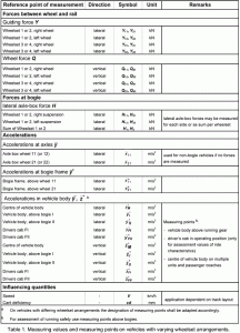
For on-track tests employing the normal measuring method, the following direct measurement are all necessary: guiding force Y and wheel force Q, accelerations at the bogie in the case of bogie vehicles, and accelerations and in the vehicle body. For on-track tests employing the simplified measuring method, the measurement of lateral axle box forces (H) must be determined using accelerations at axle boxes in the case of non-bogie vehicles, accelerations at the bogie in the case of bogie vehicles, and accelerations or in the vehicle body. Wheel/rail contact and axle-box forces must be measured on at least the two outer axles of the vehicle or one bogie, depending on whether the vehicle is fitted with axles or bogies.
Measuring points for accelerations in the vehicle body are situated on the vehicle floor. The reference point for coaches and wagons is above the bogie center; for traction units it is the driver’s cab. On multiple units and passenger coaches, accelerations must additionally be measured at the center of the vehicle body. Measuring points for accelerations at bogie frames are at one bogie frame above the two outer wheelsets. In the case of vehicles with special bogies, multiple transport units or multiple units, the scope of measurement must be adapted to the requirements.
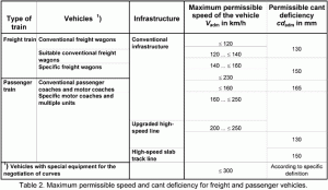
In addition to the measured parameters, speed, and cant deficiency must also be measured. Table 2 shows the specific operational parameters recommended for application during the testing of running behavior for international traffic.
![]()


