Effects of Wide Gauge on Derailment Potential (Part 1 of 2)
By Gary P. Wolf • December 1, 2004
“Wide gauge” is one of the most often used FRA derailment codes. In 2003, 254 derailments were reported to have been caused by wide gauge (FRA code T110 or T111). This represents nearly 13% of all derailments reported to the FRA, and roughly 30% of all track-related derailments. With such a significant number of derailments attributed to it, all eyes should be trained on identifying wide gauge before a derailment occurs.
The question is: Are “wide gauge” derailment conditions simply a track problem? Or can the root cause of a wide gauge derailment actually have a mechanical origin?
Gauge is nominally set at 56 1/2 inches in North America. As wheelsets roll through a curve, the wheels on both the high and low rails produce an outward, lateral, gauge-spreading force. Track with timber ties and cut spike fasteners is fairly elastic under lateral forces of approximately 20,000 pounds or less. That is, the gauge might spread slightly, but after the train passes, the gauge snaps back to its original dimension. However, when lateral, gauge-spreading forces exceed 20,000 pounds, permanent deformation of the ties and fastening system can occur. That is, the gauge no longer snaps back to its original dimension, but stays in a wider position than originally set.
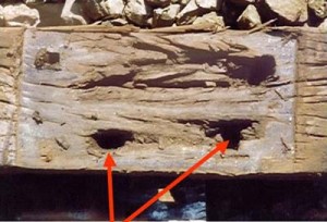
On a microscopic basis, wood fibers around the spike are compressed and deformed slightly. The spike itself might bend. In total, the gauge is incrementally and permanently widened from its initial position by the repetitive application of lateral wheel loads. And those few wheelsets producing the highest lateral loads have the potential to do the most and permanent damage. Eventually, the spike holes become elongated to the point where the spikes are loose, and often work themselves up out of the spike hole. (Figure 1 shows an example of elongated spike holes.)
In addition to elongation of the spike holes, the roll moment on the rail produced by the combination of lateral and vertical wheel forces causes the wood fibers under the outer edge of the tie plate to become permanently compressed, resulting in the rail canting outward. As the rail cants outward, the gauge is opened up at the gauge corner of the rail head.
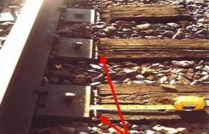
The lateral tie plate displacement due to elongation of the spike holes and the outward roll of the rail due to canting combine to produce a dynamic widening of the gauge that can result in wheels dropping down in the gauge, resulting in derailment. (Figure 2. shows an example of dynamic gauge widening in a curve. Note the evidence of lateral plate movement outward in the presence of gauge-widening wheel forces.)
Two additional sources of gauge widening are wear on the gauge face of the rail — particularly the high side of curves — and wear in the shoulders of the tie plate. Many railroads consider changing rail when gauge-face wear approaches 1/2 inch. Tie plate shoulder wear is typically in the range of 1/8 inch to 1/4 inch total, and is not a major contributor to gauge widening. In order to determine the total gauge widening in the track, four factors must be added together:
- Lateral plate movement due to elongation of spike fasteners.
- Lateral displacement of the rail head due to negative rail cant.
- Gauge-face wear on the head of the rail at the gauging line.
- Wear in the shoulders of the tie plate allowing rail movement.
If the total gauge exceeds roughly 59 to 60 inches, derailment becomes almost certain. This factor is somewhat variable due to FRA allowances for wheel flange wear. As wheels wear to a thin flange condition, the safety margin is further reduced by approximately 1/2 inch.
Wide gauge is undesirable for two primary reasons: 1) The safety margin for wheel drop is reduced; 2) The steering capability of the wheelset is compromised.
Wheelsets are pressed on the axle with a back-to-back dimension of nominally 53 inches. Given that the wheel tread area is approximately 3 inches wide, if the gauge widens by about 3 inches, the wheel tread can slip across the head of the rail and drop down. This would indicate that 59 1/2-inch (56 1/2 + 3 inches) gauge is the safety limit. However, if the flange is worn on the opposite wheel, 2 1/2 inches of gauge widening may be sufficient to allow wheel drop, or a total gauge of 59 inches (56 1/2 + 2 1/2 inches). Thus, pre-existing wide gauge in the range of 58 inches means that only an additional inch of dynamic rail movement could result in wheel drop. This is one reason that the FRA limits maximum gauge for Class 1 track to 58 inches. For Class 3 and 4 track, the maximum allowable gauge is 57 1/2 inches.
The FRA gauge standards from Section 213.53 of the federal Track Safety Standards are presented in Table 1.
Wide gauge also affects the ability of wheelsets to steer around a curve. A new and properly tapered wheelset moves to a larger diameter on the outside rail of the curve, and a smaller diameter on the inside of the curve. This creates a radius differential of several millimeters, and a net steering moment on the wheelset. In the real world of railroading, many wheels become hollow worn, creating a false flange on the outside edge of the tread. As gauge becomes wider, the probability of the false flange being pulled up onto the head of the inside rail becomes greater. The false flange is often a larger diameter than the flange root area, and consequently creates a reverse steering moment for the wheelset. If the wheelset doesn’t steer, the truck warps, and gauge spreading forces increase even higher. Thus, pre-existing wide gauge in a curve has the two-fold effect of 1) lowering the safety margin for wheel drop, and 2) increasing the gauge-spreading forces that lead to gauge widening. In academic terms, you get the “double whammy.”
Part 2 of “Effects of Wide Gauge on Derailment Potential” will explore the many causes of “wide-gauge” derailments, and how to spot the telltale signs of impending wide gauge. Part 2 also will examine instances in which “wide-gauge” derailments may not be the result of a track problem.


