Optimizing Wheel and Rail Profiles on Amtrak’s Northeast Corridor
by Eric E. Magel • September 20, 2004
Wheel wear is an inevitable byproduct of wheel/rail interaction. Excessive wear, however, indicates an imbalance in some aspect of the wheel/rail interface. Amtrak’s high-speed Acela trains, running on track with much greater curvature than other high-speed systems, were quickly found to exhibit very high rates of wear. Recognizing that this and other wheel/rail performance issues were best addressed through a proper, systemic approach, the Federal Railroad Administration (FRA) sponsored a program directed at developing methods for improving wheel/rail performance on Amtrak’s Northeast Corridor (NEC). The study focused on wheel and rail profiles, friction management and rail profile grinding, and led to the development of a new Amtrak wheel profile.
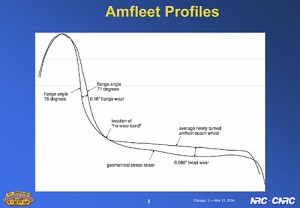
High rates of wheel flange wear on the high-speed Acela trains may have been the catalyst for the investigation, but the study also considered the conventional Amfleet cars and the 16 other commuter and freight railroads that operate over the same track on the corridor. Among the considerations are the unfavorable wheel wear patterns on the conventional fleet, which include a geometrical stress raiser that develops between adjacent running bands on the wheel and leads to high stresses on the wheels and the rail (see Figure 1). Also of concern are hollow-wheels with a false flange condition that impairs wheelset steering and damages the low rail in curves.
While wheel/rail performance can be characterized by randomly sampling wheels and rails on a system, each wheel and each section of rail tells only one story. To obtain a system-wide story, engineers from the National Research Council of Canada’s Centre for Surface Transportation Technology (CSTT) performed a Pummeling Analysis — a look at the distribution of wheel-to-rail contacts across the system — to characterize how a wheel or section of rail is shaped by wheel/rail interaction, and to validate the performance of custom-designed profiles. This examination enabled researchers to assess the damage contributed by all of the wheels—new wheels, worn wheels, leading axles, trailing axles, heavy axle loads, light axle loads — passing a specific section of track.
The contact distribution was evaluated through a computer model that superimposes a set of measured wheel profiles on a given pair of rail profiles and performs a quasi-static curving balance. Information on the vehicle’s weight, axle load, speed and truck characteristics, along with track parameters such as gauge, curvature and super-elevation, are used to model the wheel/rail interaction. The information generated by the Pummeling Analysis provides a practical method for identifying the position and severity of the wheel/rail contacts and determining the longitudinal creepage, rolling radius difference and contact stress associated with each.
Sharable, Expandable Database
CSTT worked with Amtrak’s comprehensive Sharable, Expandable Database (SED) to understand track conditions on the corridor (see sidebar Monitoring Vehicle/Track Interaction on Amtrak’s NEC.) Track geometry data in the SED, which is updated about every two weeks, includes data on the track gauge, curvature and superelevation for any point on the track between Boston and Washington. Measured rail profiles, collected at 4 1/2-foot intervals across most of the NEC by Advanced Rail Management under subcontract to the FRA, were also employed in the analysis. A speed and braking torque profile for an Acela train was provided by ENSCO, Inc. and imported into the SED database.
A comparison of the wear performance of the unworn Amtrak-Standard wheel, which measured profiles at three stages of wear, and the new CSTT-designed wheel profile was performed using CSTT’s pummelling software. Thirty-six thousand curving simulations were run for each profile to determine the distribution of the frictional work (which is generally accepted as a good proxy for wear) experienced as the train runs the full length of the NEC mainline from Washington to Boston. This evaluation determined that the frictional work at the flange root of the new wheel profile design is about half of what it is on the Amtrak-Standard wheel-profile design.
While the unworn Amtrak-Standard wheel makes very little contact with the gauge corner of worn rail, because of its strong two-point contact it encounters frequent gauge-face contact with the outside rails in curves on the corridor. The new CSTT design makes fewer gauge-face contacts over the same length of track.
Wear is only one parameter for evaluating wheel/rail performance. Another is “effective conicity,” which represents a weighted average of the rolling radius difference. When tapered wheels in tangent track are shifted sideways, the contact point on one wheel moves toward the flange throat of the wheel, while the contact point on the other wheel moves toward the field side. This creates rolling radius difference in which one wheel is rolling on a bigger radius than the other. Rolling radius difference on a fixed axle generates longitudinal creep forces that initiate a steering moment, which usually steers the wheelset away from the curve and back toward the center of the track. As the wheelset passes the centerline of the track, a steering moment is generated in the reverse direction, forcing the wheelset back toward the curve. Depending on the damping in this system, this movement will either be damped within three or four cycles or it will lead to a flange-to-flange, hunting motion.
Designing a New Wheel Profile
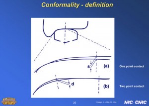
CSTT also looked at wheel/rail conformality — whether there was typically one- or two-point contact on the corridor — by positioning a wheel on rail in a curve (see Figure 2). Gaps greater than 0.4 mm between the two points of contact — one toward the top of the rail and one toward the gauge corner or face of the rail — constituted non-conformal, two-point contact. Gaps of 0.4 mm or less were considered conformal contact. Very small gaps of less than 0.1 mm between the profiles were considered closely conformal contact.
Wheel profiles on the Acela fleet generated non-conformal two-point contact, a condition that is dominated by wear. A large percentage of the wheels on Amtrak locomotives, however, generated non-conformal single-point contact, which is generally associated with high stress, hard gauge-corner contact and rolling contact fatigue. These locomotives are believed to be responsible for a disproportionate amount of contact fatigue.
To improve wheel wear on the corridor, CSTT incorporated the flange root geometry of a worn wheel with the existing Amtrak-Standard wheel flange, while maintaining a 1:40 tread taper on the wheel. By modifying the flange root geometry of the wheel, wear and contact stress at the gauge corner were reduced by half. L/V ratios were also reduced and steering improved. Contact stresses were reduced without increasing the tendency for hunting.
Using the same Pummeling Analysis on rail, CSTT developed four new rail profiles to reduce wear and optimize the overall wheel/rail interface on the NEC. These include profiles for a sharp-curve high-rail, a mild-curve high-rail and two profiles for tangent track. One of the tangent profiles is also used on the low-rail in curves. From Amtrak’s perspective, the most significant change is being made to tangent track. The use of two profiles for tangent track—one that biases contact toward the gauge, and the other toward the field—actively spreads contact across the wheel tread. This helps reduce wear at any one point on the wheel, which inhibits hollowing and helps the wheel maintain its design shape for a longer period of time. At the same time, stability is improved since the effective conicity for either running band is generally lower than the existing single wide running band. This family of new rail profiles provides better overall performance with the existing population of worn wheels. When combined with the new wheel profile, they are expected to contribute to a doubling or tripling of wheel wear life and a reduction in rail contact fatigue. They will also improve high-speed stability and reduce the amount of rail profile grinding work needed in the future.

Eric E. Magel is Senior Engineer, Rail Division at the National Research Council of Canada’s Centre for Surface Transportation Technology.


