Wheel/Rail Interaction ’08: Data to Information (Part 2 of 2)
By Jeff Tuzik • October, 2008
Part 1 of this article examined efforts to optimize vehicle and track component performance through various testing, monitoring and simulation programs. Part 2 continues on the theme of “data to information,” further exploring such programs and the operational benefits they engender.
Maintaining a Safe Neutral Temperature (SFT) on CWR has been an ongoing challenge for railways. Because of the danger of track buckling, which occurs at high temperatures, and rail breaks, which occur at low temperatures, railways and suppliers have been working to develop a practical, reliable and affordable means of measuring and monitoring the neutral temperature on CWR.
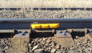
Canadian National worked with IDERS Engineering to develop a wireless system to monitor the SFT on CWR in order to detect track buckles and rail breaks, and emerging problems that are related to temperature changes, tonnage, track and surfacing work.
CN wanted a low-cost tool that would provide lifetime accuracy without the need for ongoing calibration — a tool that was rugged and robust, required no service or service parts, that was easy to install, and could be interrogated wirelessly, said IDERS President Bradley Brown.
To be acceptable to CN, an SFT measurement system needed to provide accurate measurements in all weather conditions (-40 degrees C to +70 degrees C) and require no ongoing service or calibration requirements. The system must provide an “instant” wireless SFT read-out that can be read at speed by roadmasters, tampers or defect detection cars (up to 20 mph).
The IDERS SFT measurement system, which is currently being implemented on CN, utilizes a sensor that is mounted to the rail and calibrated with known strain or SFT. As the stress-free temperature rises, the rail and sensor stretch. This change in dimension produces a drop in sensor resonant frequency, which is proportional to the change in strain. As the stress-free temperature drops, the rail and sensor compress. This change in dimension produces an increase in sensor resonant frequency which is proportional to the change in strain.
CN hopes that the SFT measurement system will enable track crews to find and fix problems on a proactive basis, and will provide CN and contract crews a verification and quality control tool.
Target Profiles for Rail Grinding
The removal of metal at the right time and in the right place is a fundamental aspect of rail maintenance work. This sounds simple enough, but it’s easier said than done.
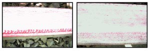
The early days of rail maintenance often saw excessive metal removal in order to correct surface irregularities and defects that had, or would, cause severe problems. Today, rail maintenance practices have taken great steps toward becoming preventive measures. In contemporary rail grinding programs, thin layers of metal are removed at regular intervals to keep rail profiles within tight tolerances and prevent the types of conditions that require significant metal removal, said Wolfgang Schoech, Manager External Affairs at Speno International SA.
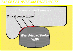
An effective “preventive” approach requires the “right” profile or profiles to be applied. Since rails are installed at different locations and traffic characteristics change, there isn’t a single profile that suits all conditions. In Europe, profiling started with aiming at the as-rolled shape of new rails. “Experience showed that this “re-profiling” was not always the best solution,” Schoech said. As a result, various, more specialized profiles were developed. These profiles have undergone long in-track testing and today a number of unique profiles are routinely ground.
European railroads currently employ a number of specific profiles, including wear-reducing asymmetric profiles, fatigue-reducing anti-headcheck profiles, and various profiles increasing running stability. Occasionally, no existing profile best fits a certain scenario and an entirely new profile must be developed. This was recently the case for Banverket, a heavy-haul railroad in northern Scandinavia. Banverket undertook a meticulous process to develop the rail profile that best matched its hollow-worn wheels, in order to optimize both wheel and rail service life, he said.
“Ongoing creation, and revision of rail profiles is intrinsic to ensuring that grinding remains a preventive measure, that metal removal be minimized, and that rail service life be fully exploited,” Schoech said.
Evaluating the Risk of Wheel Climb
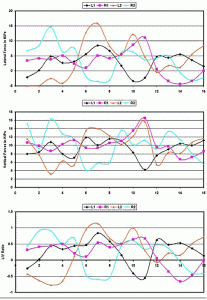
For many years now, the L/V ratio has been the industry standard for evaluating wheel climb risk; in recent years, the expanding network of wayside detector units has made it easier than ever before to take accurate and frequent L/V measurements. Recent research funded by the Federal Railroad Administration (FRA) and performed by the National Research Council of Canada’s Centre for Surface Transportation Technology (CSTT) suggests that additional parameters may be necessary to accurately gauge wheel climb potential in certain scenarios.
Common knowledge, supported by L/V measurement data, holds that one-point contact carries less risk of wheel climb than two-point contact, said Yan Liu, Senior Engineer at the NRC-CSTT. However, using only the L/V ratio to model this condition presents a technical dilemma. Under two-point contact conditions, the standard L/V ratio loses its essential meaning because the total lateral and vertical force between the wheel and rail is shared by both points of contact. Therefore, when the L/V of a two-point contact wheel is measured by a wayside detector, the data does not represent the true L/V of the wheel in a potential wheel climb scenario.
Using a formula (V2/V) that includes both points of vertical force on a non-conformal wheel, in conjunction with the standard L/V ratio, the NRC-CSTT research demonstrates a more reliable measure of the wheel climb potential of a two-point contact wheel, Liu said.
The NRC-CSTT research also modeled various lubrication conditions to better understand the effects of gauge-face and top-of-rail (TOR) lubrication on wheel climb potential. This battery of simulations indicated in all of the scenarios tested (loaded and empty cars, one- and two-point wheel contact, and varying levels of lubrication) that lower friction at the gauge-face results in lower overall wheel climb potential.
The NRC-CSTT simulations can also be applied to further study on cant deficiency, car types, and truck characteristics to develop a more thorough understanding of wheel climb dynamics, Liu said.
Top-of-Rail Friction Control
Railroads have long used gauge-face lubrication as a means to extend rail life. More recently, they’ve introduced innovative TOR friction modifiers to supplement gauge-face lubrication and further reduce wear associated with lateral forces. But rail life extension is not the only benefit to be reaped through implementation of TOR friction control.
To better understand, and better quantify the benefits of TOR friction control, the Transportation Technology Center, Inc., (TTCI) conducted a two-year survey of TOR friction control application systems (both wayside-based and mobile systems) at a number of field sites. The survey confirmed the benefits of TOR friction control systems and reiterated some of the limitations, as well.
Curving forces and rail wear both showed significant reductions under TOR friction control. Energy consumption was also reduced. Results also indicate that TOR friction control has no negative impact on braking or wheel wear. The effectiveness of wayside and mobile application of TOR friction modifiers was reduced, however, under heavy braking, indicating that route characteristics must be carefully considered.
Understanding the benefits and limitations of TOR lubrication is an important step in the right direction, said Richard Reiff, TTCI Principal Investigator. The next step is further study of application strategies in order to fully exploit the benefits and minimize the limitations. There is potential to further optimize applicator output rates and spacing on wayside systems, and applicator deployment strategies on mobile-based systems.
Automated Track Inspection
The Federal Railroad Administration (FRA) Automated Track Inspection Program (ATIP) has been collecting track geometry, ride quality and other track data on the U.S. rail network since 1974. The ATIP program employs several geometry cars and the Track Data Management System (TDMS), which was designed to streamline track data manipulation, data viewing, record keeping and route scheduling.
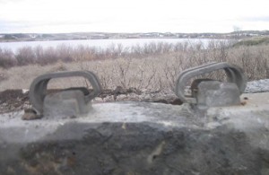
In light of recent rail rollover derailments citing rail seat abrasion of concrete crossties as a contributing factor, these technologies have recently been brought to bear on rail cant problems related to concrete ties, said Arthur Clouse, Program Manager, Automated Track Inspection Program, in the FRA’s Office of Safety, Assurance, and Compliance. The FRA established a Rail Seat Deterioration Task Force to determine the derailment circumstances, develop a better understanding of rail seat deterioration and failure, and to provide recommendations to the Rail Safety Advisory Committee (RSAC).
In conjunction with FRA investigations, Volpe National Transportation System Center conducted numerical simulations and analytical studies to illuminate the role of track geometry, and resulting forces, in the development of rail seat abrasion. Analysis of the track geometry data from the derailment sites indicated that combinations of profile and alignment irregularities contributed to the derailments, and that these irregularities were within FRA Class 3 geometry limits. Based on simulations, the present irregularities produced powerful dynamic responses and increased crosstie loads beyond acceptable limits.
To better understand the factors associated with types of derailments, ATIP conducted geometry surveys with the FRA’s DOTX 216 geometry vehicle. Data from the surveys was used to develop techniques to identify problematic sites.
Surveys measuring rail cant on a foot-by-foot basis allowed ATIP to develop and test “alarm” and “alert” cant thresholds. Follow-up inspections on concrete crossties identified as problematic during surveys confirmed that rail cant measurements are effective in identifying locations of concern, Clouse said. The FRA is also working on methods to identify other indicators of failed concrete crosstie systems, such as base gauge, relative rail roll, and gauge widening.
The RSAC Concrete Crosstie Task Force continues to assess the issues and is expected to provide recommendations and measurement parameters that will help identify concrete crosstie deterioration.
Condition Monitoring
Frequent inspection and monitoring of infrastructure and rolling stock has become a vital part of day-to-day railway operations. As railroads and car owners have sought to expand their inspection regimes, technology has kept pace — and the number of inspection/monitoring tools and systems continues to grow.
The “you can’t manage what you can’t measure,” adage holds true, said Ryan McWilliams, Vice President of Technology and Business Development at Salient Systems Inc. But as the array of inspection tools grows, it’s important for industry leaders to know the strengths and limits of the available options.
The essential purpose of Condition Monitoring is to monitor the health of rolling stock and rail. wayside and rail-mounted detectors present the most efficient and cost effective method of doing so, McWilliams said. To maximize the effectiveness of data collected through such means, systems must be in place to process the data in real time and generate clear information that railroads can act on. Since different tools measure different aspects of railroad operations, a combination of tools is often necessary to monitor the health of a railroad.
Truck Performance Detectors (TPDs) measure a critical aspect of vehicle dynamics by identifying skewed or hunting trucks. These detectors are able to associate measurements with individual wheels, axles and trucks and forward results — and alarms, where appropriate — to wheel data management systems.
TPDs measure interactions at the wheel/rail interface to evaluate vehicle performance and identify irregularities. These systems are able to associate symptoms with causes to ensure that the right kind of maintenance is performed. Gauge spreading, wheel unloading, truck warp flange climb, track panel shift and rail rollover, for example, are all typical of very different root problems, McWilliams said. TPD evaluations help eliminate the guesswork from correcting these issues.
“The right monitoring tools ensure that maintenance dollars are spent when and where they’re needed most,” McWilliams said. “Decision-makers must be attuned to which technologies best fit their condition monitoring needs.”
![]()

