Wheel/Rail Interaction ’08: Data to Information (Part 1 of 2)
By Bob Tuzik • July, 2008
As research into wheel/rail interaction has evolved, the emphasis has moved toward implementation of available technology and conversion of data into information. Such was the case at Wheel/Rail Interaction ’08, the 14th annual seminar produced by Advanced Rail Management and sponsored by Progressive Railroading magazine. Railroaders, researchers and suppliers presented information on current efforts to improve the performance of vehicle and track components and the overall operating parameters associated with vehicle/track interaction.
Norfolk Southern (NS) presented some initial findings of a pilot program to implement electronically controlled pneumatic (ECP) braking on a portion of its coal fleet. As of May 2008, NS is operating six ECP train sets in two operating regions. The project, which is supported by the NS Coal Business Group, Mechanical Department and Research & Tests, along with the Association of American Railroads (AAR), Transportation Technology Center, Inc. (TTCI), and Federal Railroad Administration (FRA), is designed to quantify the performance, safety and cost benefits of ECP braking.
Factors that led NS to implement ECP braking include:
• Shorter stopping distances, which will improve collision avoidance and allow for better signal spacing.
• Elimination of derailment-causing slack action, and better distribution of braking forces through the track.
• Extended mileage intervals for required Class I inspections.
• Reduced wheel change-outs due to slid flats.
• Reduced fuel consumption.
NS has been operating (under an FRA waiver) two 115-car train sets of gondolas in Pennsylvania; two 100-car train sets of automatic dump cars in Virginia; and two 85-car train sets of automatic dump cars in North Carolina.
“The crews and supervisors love them,” said Walter Rosenberger, NS Operations Engineer – Research and Tests.
Results from Pennsylvania indicate that stopping distances under a full service brake application for a loaded train traveling at 31 mph were 1,227 feet, compared to 2,242 feet for a conventional braking system — a 45% reduction in stopping distances.
NS plans to continue testing to further asses the benefits of ECP braking on its fleet in various corridors.
Curving Resistance
With the recent surge in fuel prices, railroads are taking a broader perspective on fuel consumption and operating efficiency.
“Fuel consumption is a function of several factors, including the resistance generated by freight cars while traveling through curves,” said Matthew Dick, Assistant Vice President of Engineering and Dynamic Studies, at Rail Sciences, Inc.
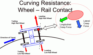
Since freight car axles are rigid and restrained in a three-piece truck, micro-slip occurs at the wheel/rail contact patch during curving. This micro-slip, known as “creepage,” and its energy loss is equivalent to the resistance of freight car steady-state curving. While many factors can affect creepage, Dick said, the two primary factors that can be controlled through train operation are coupler force and train speed.
Rail Sciences evaluated these variables using VAMPIRE™ vehicle dynamics software to simulate a nominal coal car in a unit train in both loaded and empty conditions in order to determine the influences of coupler force and train speed on freight car curving. Incremental coupler loads from 350 – 350 kips and train speeds from 10 – 60 mph were simulated on curves up to 16 degrees.
Results indicated that buff coupler loads and overbalance speeds produced favorable or neutral effects on curving resistance, while draft coupler loads and underbalance speeds created unfavorable effects on curving resistance.
While important, curving resistance is just one of many types of resistance on a moving train, Dick said. Inertial and grade-related forces, suspension damping, track deflection, bearing and wheel/rail friction are also at work. Energy loss through wheel/rail contact and vertical and lateral track deflection were also investigated.
Rail Sciences used a Train Operations Simulator (TOS) to model a specific 200-mile mainline route with maximum grades of +/- 1.2% and 8 degrees maximum curvature. Train handling was selected by the TOS automatic train handling algorithm (to maintain target 30-, 40- and 50-mph speeds). Simulations were run in both directions with the actual curvature and on tangent track with all curves removed.
VAMPIRE™ simulation indicated that curving resistance could realistically be reduced by 30% – 40%, best case, and 15% to 20% on average. The lowest curving resistance generally occurred at higher speeds and higher buff drawbar forces.
The simulations further projected that the total train resistance could be reduced by modifying train speed and drawbar forces by no more than 3.3% in the best-case scenario, but more typically by less than 1%. Simulations further determined that these reductions may be negated by increased speed — more locomotives and increased aerodynamic and suspension damping resistance. As a result, Rail Sciences concluded that modifying train speed and drawbar forces does not appear to be an effective way to reduce train resistance and fuel consumption.
Rail Testing
The AAR and FRA have jointly funded a revenue service “mega site” testing program to help North American freight railroads implement heavy axle load (HAL) operation and mitigate its effects on track degradation. Track-related experiments at mega sites on Norfolk Southern and Union Pacific coal lines supplement the HAL testing at FAST (Facility for Accelerated Service Testing) by providing a wider range of track, subgrade, operating and environmental conditions.
The revenue service experiments were designed to quantify how HAL operation affects track component degradation, to test new designs and track materials, and to improve track maintenance procedures in order to reduce the forces applied to the track. The performance of premium rail, including resistance to wear and defect growth, under heavy axle loads in revenue service was also evaluated.
The Eastern mega site was established on four (6.8- to 10-degree) curves on a 55-MGT, timber-tie track with excellent gauge-face lubrication and top-of-rail lubrication friction control. Operating speeds are 20 – 30 mph. The Western mega site was established on three (1- to 2-degree) curves on a 240-MGT, concrete-tie track with 141-pound premium rail with fair gauge-face lubrication and no top-of-rail lubrication friction control. Operating speeds are 50 mph.
Dingqing Li, Senior Principal Engineer at the Transportation Technology Center, Inc., reported that (assuming a maximum 5/8-inch gauge-face or head wear), all test rails have exhibited excellent wear performance with a minimum estimated wear life of:
• 2,800 MGT for a 2-degree curve with “fair” gauge-face lubrication and no TOR friction control.
• 1,000 MGT for a 10-degree curve with “excellent” gauge-face and TOR friction control.
• 560 MGT for a 5-degree curve with no lubrication (39-ton axle loads).
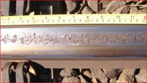
Rolling Contact Fatigue (RCF) was not an issue at up to 150 MGT, Li said. While no RCF appeared in rails in a 1-degree curve after 610 MGT, significant RCF did occur on the low rails of 2-degree test curves at the UP site within 300 – 350 MGT. Contributing factors include:
• Very dry rail surface (friction coefficient above 0.5).
• Poor geometry at welds. (More than half of the RCF defects were concentrated around plant welds.)
• Under-balanced speed, which caused higher normal and tangential wheel/rail forces on low rails, particularly on the 2-degree curves.
Other possible factors include wheel and rail profiles, and the warp stiffness of trucks.
Generally, Li said, all premium rails in the tests have exhibited excellent wear performance under HAL operation. No internal defects or broken plant welds were identified during the test. Without preventive grinding, RCF started to become significant on the low rails in 2-degree curves after 300 – 350 MGT. All of the premium rails in the tests showed work-hardening effects, with hardness measurements of more than 400 BHN.
Vehicle Testing
Efforts are also underway to quantify and improve the performance of railway vehicles and components. TTX Company, for example, has established an ongoing R&D program to evaluate trucks and truck components at the TTCI facilities in Pueblo, Colorado. TTX’s research there is focused upon improving the performance of cars and components, and on lowering the operating costs for cars used in the TTX fleet. The basis for much of the testing is from the AAR Manual of Standards and Recommended Practices, Chapter XI service worthiness test standards and procedures. The recent M-976 standards for the interchange of 110-ton cars has led to a growing number of adapter-pad equipped cars entering the TTX fleet.
TTX began voluntary compliance with the S-286 specification for free interchange of 286,000-pound gross rail load (GRL) cars in 2003, and is currently engaged in an extensive R&D effort to monitor and quantify the performance of M-976 trucks on all TTX car types.
As the M-976 trucks in the fleet have begun accumulating significant mileage, TTX R&D has also engaged in a test program to compare standard roller bearing adapters to adapters with pads, along with the baseline curve negotiation data, said Jon Jeambey, TTX’s Director of Research and Development. Distance-measuring lasers have been added to the instrumented wheelsets to record wheelset angle-of-attack in order to help researchers understand the role of adapter pad motions during curving.
TTX has determined that adapter pads are a key performance component of its truck designs. M-976 truck types and side bearing types are familiar to TTX, but this is the first widespread use of adapter pads since the articulated doublestack cars in 1986 – 1992 era.
“We’re concerned by how little we know about the function of adapter pads,” Jeambey said.
Tests of adapter pads in the early 1990s indicated that the pads’ properties had both positive and negative effects. While they reduced wheel shelling in TTX service tests and lowered wheel/rail forces in most cases, decreased truck warp restraint and high-speed instability (and an assumed short life due to constant flexing of the pads) prevented TTX from approving their use in its fleet.
TTX plans future testing of M-976 truck designs to determine pads’ influence on rolling resistance, speed stability and truck warp in curves with high rail lubrication.
Wheel Shelling and Spalling
Wheel maintenance is another primary area of concern relating to vehicle/track interaction.
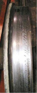
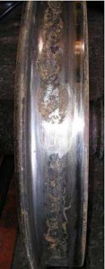
“Wheel tread damage, primarily in the form of shelling or spalling, costs the railroad industry $350 million annually,” said Scott Cummings, Senior Engineer at the Transportation Technology Center, Inc.
The Wheel Defect Prevention Research Consortium (WDPRC), which includes Class I railways, the FRA, private car owners and industry suppliers, was formed to determine the actions, events, and mechanisms that initiate wheel damage, and to identify remedies. The WDPRC’s findings are based on a range of activities, including inspections, controlled condition tests, data recorded during revenue service operations, and computer modeling results. The primary defects are:
• Slid flats and spalling: A wheel sliding on the rail creates enough heat to produce a metallurgical transformation and eventually to produce a spall.
• Fatigue and shelling: Repeated cycling of stresses causes cracks to form and eventually produce a shell.
The WDPRC determined that nearly half of the 700,000 wheelsets changed out in 2006 were due to tread damage-related causes (Why Made Codes 61, 65, 67, 75, and 78).
The WDPRC used data from various sources to determine root causes. Sources included inspections of damaged and undamaged wheelsets from good and bad actor cars; controlled condition testing of air brake valves, brake shoe forces and drag brake thermal testing; analysis of data from Wheel Impact Load Detectors (WILD) and wayside wheel temperature detectors; and computer simulation of wheel sliding and wheel fatigue.
Analysis of 163 wheelsets (with Why Made Codes 11, 61, 64, and 65) were inspected. Etchant was applied, radial runout was recorded, and the type of damage was tied to the type of car and service. Analysis indicated that shelling was the primary defect on coal cars, a mix of spalling and shelling (primarily spalling) on non-coal cars, and thermal mechanical shelling on intermodal cars.
Movement of cars with handbrakes applied was shown to be the primary cause of wheel spalling. Previous analyses have shown that cars with truck mounted brakes have more tread damage to the wheels on the “B” end. The WDPRC analysis further reinforced this, finding a 95% to 5% split for a group of 294 tank cars.
NUCARS® simulations of cars traversing rough track that excited suspension bounce resonance determined that empty cars (especially those with malfunctioning E/L devices) can slide wheels under heavy braking in low wheel/rail COF conditions, regardless of track geometry, and may be a minor source of spalling.
The WDPRC analysis found that most Rolling Contact Fatigue (RCF) damage occurs on the low rail wheel of the wheelset in the lead position of the truck on loaded cars during curving. These findings were further supported by wheelset inspections, revenue service instrumented wheelset data, WILD data and NUCARS modeling. Analysis of data from instrumented wheelsets on a loaded coal car through 1,500 miles in revenue service indicated some level of RCF was likely to occur on curves of 4 degrees or greater, and in instances when the trains were operated below the curve balance speed.
Data from a wheel temperature detector installed near the bottom of a hill, which analyzed more than 600,000 wheelsets on 1,575 trains, indicated that 76% of the descending cars with a wheel temperature greater than 500 degrees F had only a single wheel above this level. While the wheels in these cars were generally at higher temperatures than the wheels of other cars in the train, there were large temperature differences between individual wheel locations. Repeated hot wheel behavior was found on 37% of the descending cars with hot wheels, and at 20% of individual hot wheel locations.
The cause of hot wheel behavior within cars and between cars is difficult to identify, Cummings said. One car was found with a handbrake applied; no cause was found for 14 other cars that were inspected. A detailed inspection/teardown and brake tests indicated that the selection of bad and good actor cars based on wheel temperatures correlated well with wheelset replacements. “Bad actors had twice as many replacements,” Cummings said.
The WDPRC recommends increased adherence to handbrake release policies to reduce wheel spalling. Operators should minimize the use of train brakes and maximize the use of dynamic braking, especially in regions with heavy grades, to reduce average wheel temperatures. The WDPRC also recommends examining the effects of rail profiles, superelevation and the coefficient of friction on the development of RCF. It recommends the use of trucks with high warp resistance and low axle steering resistance to reduce wheel/rail tangential forces during curving.
![]()


