
Better Track Geometry Through Better Ballast Maintenance
by Jeff Tuzik

Maintenance is a balancing act. Time is limited, budgets are limited, resources are limited. These limited resources and the pressure to make the most out of tight maintenance windows often drives an ethos that places a premium on the speed and performance of maintenance actions, personnel, and equipment. “Maintenance of way equipment and practices are often pushed toward the highest possible production speeds and performance metrics,” Fabian Hansmann, Head of Marketing at Plasser & Theurer, told delegates at the 2024 Wheel/Rail Interaction Heavy Haul Conference. “Too often,” he added, “the quality of their work suffers as a result.” This is the balancing act: finding the point at which performance and quality are both as high as possible without one disproportionately affecting the other.
A fundamental aspect of track design and maintenance, track geometry is also crucial element of wheel/rail and vehicle/track interaction. Its significance is such that it’s federally regulated; there are hard thresholds that govern track geometry regardless of the degree to which a railroad is interested in maintaining track or optimizing vehicle/track interaction.
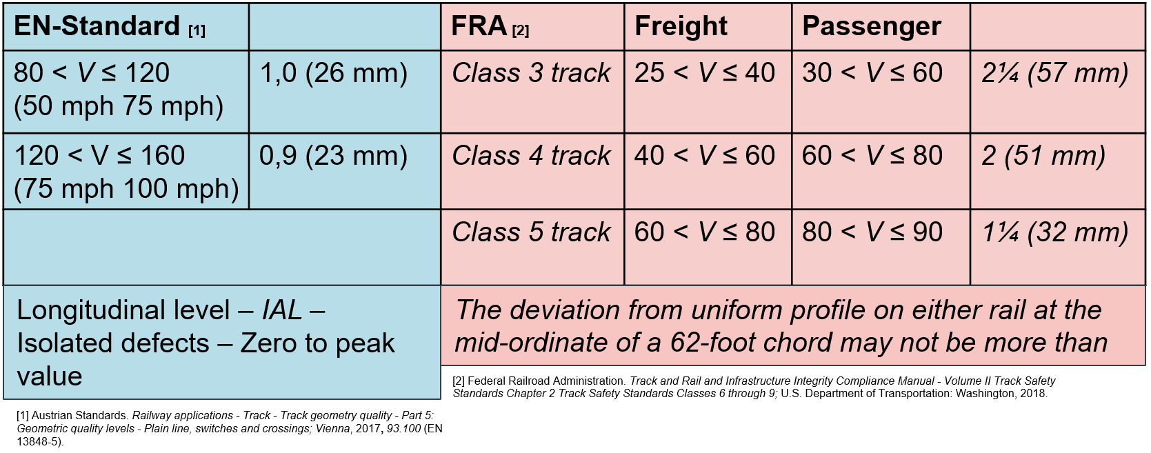
Track geometry is generally measured and evaluated through several specific parameters, chiefly: crosslevel, gage, superelevation, warp, twist, profile (vertical alignment), alignment (horizontal alignment), and curvature. Maintaining track to the appropriate level, at minimum, based on these measurements is critical to the industry in terms of safety, ride quality, and economic performance, and for regulatory compliance. The chart in figure 1 shows both FRA and European Union standards for profile (vertical) deviations, for example, for various track classes.
Of course, every railroad has a slightly different calculus for balancing the speed, efficiency, thoroughness, and precision of their maintenance-of-way programs. This is often achieved through fine-tuning and revision that takes place over countless maintenance cycles, and is a constantly moving target, Hansmann said. Part of this fine-tuning is determining how time and money should be spent on each component of the track geometry portfolio, which broadly includes rail surface, track components, ballast, substructure, and drainage.
The significance of each component varies from situation to situation, but ballast, substructure, and drainage tend to have the largest combined influence on track geometry, with the exception of gage, which tends to be closely related to tie and rail surface condition, Hansmann said.
Ballast, in particular, plays a critical role in maintaining and influencing track geometry; it is a load-bearing component in every sense. “There are four things that make ballast an ideal base for track; it is stable, permeable, maintainable, and it’s universally available,” Hansmann said. He also said that these characteristics change over the lifetime of the ballast. A combination of forces — traffic most significantly — causes ballast to settle, shift, chip, and break over time. This can lead to irregularities, “inhomogeneous settlements,” as Hansmann referred to them, that result in a variety of track geometry defects. The class of track and type of traffic it sees generally determines the level of severity a defect can reach before triggering a maintenance response.
Track profile, also called vertical alignment or longitudinal level, measures the vertical uniformity of the track over a set distance, such as a 62-foot chord. As ballast settles and compacts, it can cause the rail to dip, similar to a pothole on the road. And like a pothole, deterioration accelerates as the defect worsens, Hansmann said. These defects (or deviations) also accelerate damage to the surrounding components.
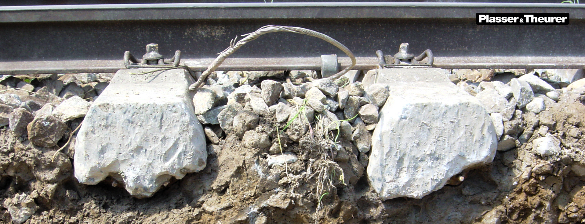
Video 1 shows a track profile defect under load. The impact forces that result from this kind of deflection damage the rail, ties, fasteners, and the ballast. If this isn’t corrected, that section of track will soon resemble the one shown in figure 2. “The ballast becomes heavily fouled and very stiff; there’s no elasticity remaining in the system,” Hansmann said. A gap of only 2.0 mm between the bottom surface of the ties and the ballast can increase tie-ballast impact loads by nearly 200% — more than enough to destroy a concrete tie over time. This kind of damage can also be initiated from the top down. High impact loads at a joint or dipped weld, for example, can cause the ballast to compress and foul, leading to a similar outcome. Regardless of where the defect initiates, as ballast condition deteriorates, so does the condition of the entire system, he said.
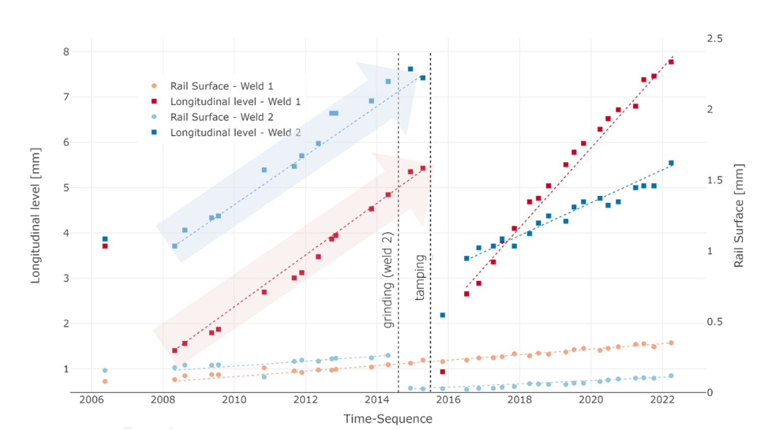
Figure 3 shows a graph comparing two nearby welds on an Austrian railroad. Both welds show comparable, progressively more severe profile geometry defects (labeled longitudinal level on the graph) over time. After ballast tamping in 2015, the two welds behaved very differently. For weld 1, the defect severity-progression-rate increased; for weld 2, it decreased. The primary difference between the two welds is that weld 2 was ground in 2015, while weld 1 wasn’t. “This shows us that rail surface has a big effect on track geometry,” Hansmann said. The combination of grinding and tamping reduced both the severity and the severity-progression-rate of the rail profile and track profile deviation at weld 2. As a result, the railroad that is the source of this data now coordinates grinding and tamping operations so that track in need of remediation gets the benefit of both, Hansmann said. “Research has shown that short-wavelength surface defects (less than one meter) with an amplitude of 0.15 mm or greater have a significant impact track geometry and deterioration rates.”
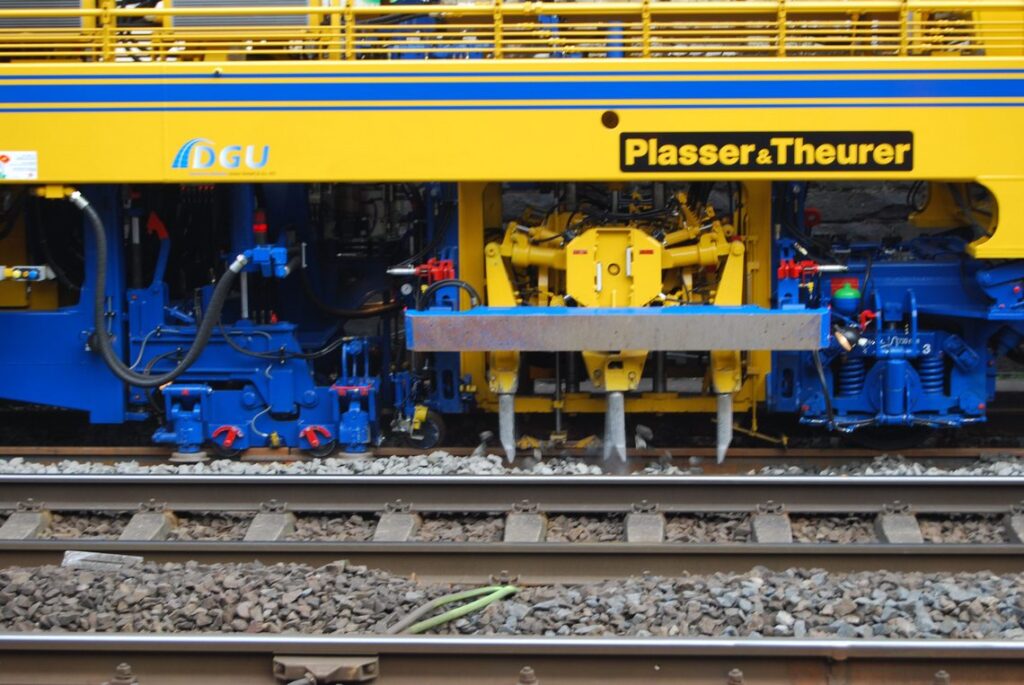
As in the example above, tamping, like grinding can have both preventive and corrective effects; although in the case of tamping, these relate to track geometry rather than surface condition. For ballast to maintain its desirable properties, it requires maintenance of its own. “The ideal ballast condition is one of homogeneous compaction,” Hansmann said. Ballast tampers [see Smart Rocks, Smart Tamper: Investigating the Mechanics of Ballast Tamping – Interface Journal for more information], which often include a rail placement/alignment function, achieve this by filling in voids that have formed in the ballast and by compacting the ballast on which the ties rest to a uniform level.
The tamping process can be further broken down into the distinct actions that make up a single tamping cycle, all of which typically happens in less than a second (see video 2):
- Lifting and lining: a manipulator lifts the rail and moves it into proper position
- Penetrating: the tamping module inserts tines on either side of the target tie
- Filling: the tamper uses a squeezing motion to move ballast into voids around the tie
- Compacting: the squeezing motion continues (combined with an oscillating motion) to compact the ballast
- Lifting: the tines withdraw from the ballast
- Positioning: the tamper moves to the next target
At every step of this process, various parameters can be adjusted to effect both tamping quality, and speed/performance. These include tamping depth, tamping force, frequency of squeezing, squeezing time, and number of insertions, Hansmann said. “It’s possible to reduce these values, such as squeezing time, to a minimum of 0.6 seconds; you’ll get good performance in terms of how much track you cover, but what will compaction quality look like?”
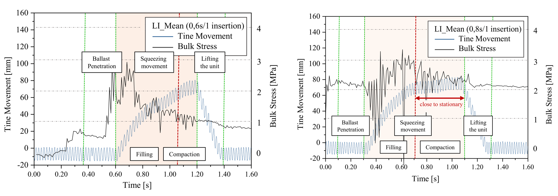
The left graph in figure 4 shows a single tamping cycle for a squeeze time of 0.6 seconds. At 0.6 seconds on the graph, the tines enter the ballast. This causes a spike in the bulk stress of ballast, which then drops off as the tines begin their compaction phase (circled in red). The graph to the right shows the same tamper in roughly the same location, but this time set for a 0.8 second squeeze time. In this case, the tines are stationary and squeezing (circled in red) for a relatively much longer period of time. This 0.2 second difference significantly changes the falloff of the bulk stress following tine insertion. In other words, a mere 0.2 seconds means more stability and better compaction, Hansmann said.
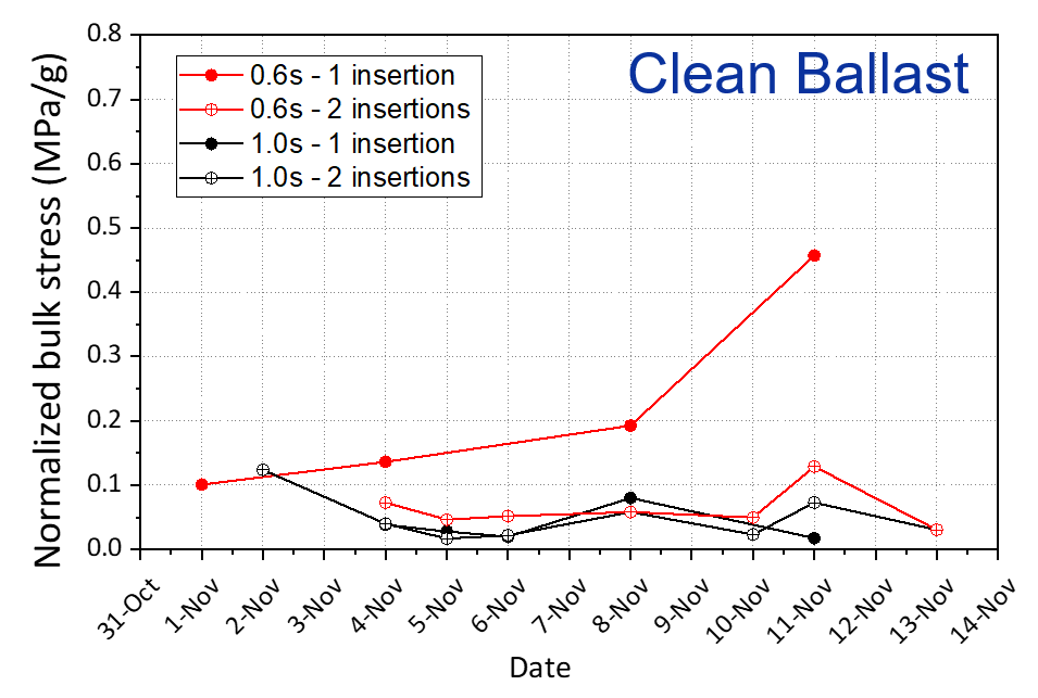
This finding holds true in larger and longer-term datasets as well. Figure 5 is a graph comparing tamping results, measured in normalized bulk stress over time, for different values of squeeze time and insertions: A) 0.6 seconds/1 insertion, B) 0.6 seconds/2 insertions, C) 1.0 seconds/1 insertion, and D) 1.0 seconds/2 insertions. According to the data, the insertions for B, C, and D, the tests that featured longer squeeze times and/or more insertions, performed similarly. The data for A, which featured a single insertion at 0.6 seconds, showed demonstrably less compaction and stability over time, Hansmann said. “This is something to keep in mind when you push for performance above all else; eventually you hit a limit where the tradeoff isn’t worth it.” From a practical standpoint, this could mean that a squeeze time of 0.6 seconds gets the entire tamping project done faster, but necessitates more frequent tamping.
A fraction of a second spent tamping doesn’t seem like it should affect track geometry much, but clearly it can. Like Hansmann said, as ballast condition deteriorates, so does the entire system. But it doesn’t deteriorate linearly. Large-scale studies have shown that declining track geometry conditions increase the dynamic impact on the entire ballast bed, accelerating the rate of its deterioration, and accelerating the deterioration of track quality indices in turn, Hansmann said. These are the kinds of trade-offs that can push a maintenance program from “good enough” to optimal. It’s also important to note that conditions on the ground are quite different from those in a laboratory or test site; performing maintenance optimally is an undertaking that requires a combination of practical experience and data-backed fine-tuning.

Jeff Tuzik is Managing Editor of Interface Journal
This article is based on a presentation made at the 2024 Wheel Rail Interaction Heavy Haul conference.
- [Loidolt, M.; Marschnig, S. 2023; The impact of short-wave effects on deterioration of track geometry, Proceedings of the Institution of Mechanical Engineers Part F Journal of Rail and Rapid Transit] ↩︎