
Using Elastic Components to Improve Rail, Tie, and Ballast Life
by Jeff Tuzik
Track condition is about more than rails and ties. It includes everything below the rail and ties, too. Track components, ballast, and subgrade are all part of the package; they all affect overall track condition. And, as Brazil’s MRS Logística’s track renewal programs have shown, improving track resilience and introducing elastic components can provide direct benefits to every part of the track, and the railway system, overall.
MRS Logística, one of Brazil’s highest-density freight railroads, operates a track network of 1,643 track kilometers (or 1,020 track miles) and primarily operates in the states of Minas Gerais, Rio de Janeiro, and São Paulo. (For more information on MRS Logística’s network, see MRS Logística: A History of Innovation and Optimization – Interface Journal.
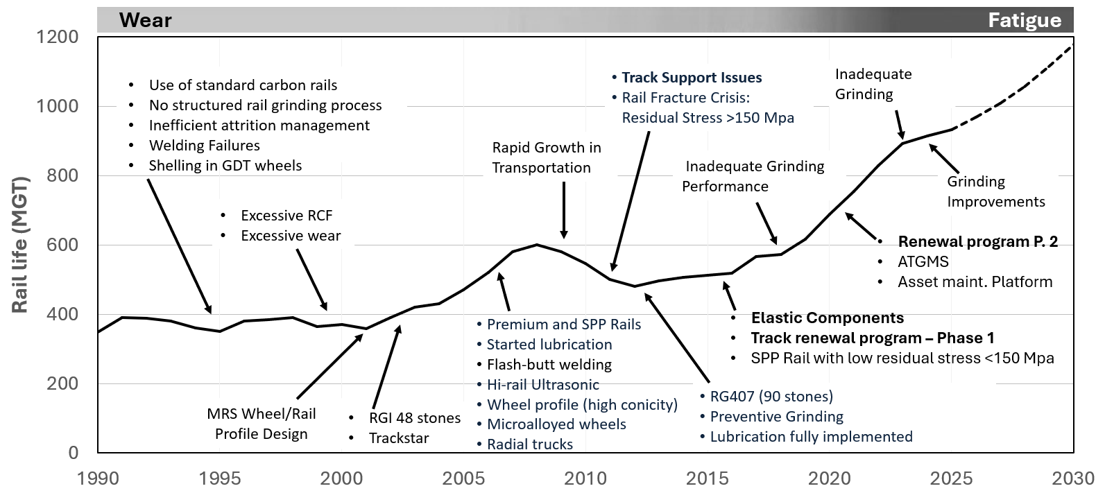
MRS Logística has undertaken a number of upgrades and system-wide improvements and optimizations since becoming the railroad’s operator in 1996 (see Figure 1 for details). Among these efforts has been, and continues to be, a focus on comprehensive track renewal: “This has included cleaning the ballast and improving drainage, adding elasticity into the track system, and moving from wood to concrete ties [an ongoing process],” Antonio Merheb, Consultant at MRS Logística and Vice-Chair of the International Heavy Haul Association (IHHA) , told attendees of the 2025 Wheel/Rail Interaction Heavy Haul Conference.
These types of optimization programs have steadily increased average rail life throughout the system from ≈400 MGT in 1996 to ≈900-plus MGT in 2025. Merheb credits the rail life gains, in part, to MRS’ focus on track substructure, including ties, ballast, and drainage, and on improvements in track elasticity (i.e. the introduction of elastic components). “On the railway, every component is affected by every other component, and the track and substructure are the foundation of it all,” he said.
Strategic Track Plan
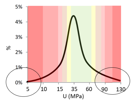
MRS’ program to improve track support, resilience, and elasticity largely took place between 2015 and 2019, although there is overlap in some of these initiatives, and some, such as rail renewal, are ongoing. Early on in the program, MRS conducted preliminary studies to gather data on track modulus and ballast conditions. Figure 2 shows track modulus data from 2015. MRS’ average modulus was measured to be 33 MPa, “but we had zones of concern that were spread throughout the entire system,” Merheb said. Track modulus that is either very low or too high can be detrimental to rail. Very low track modulus, such as is often found in fouled ballast/mud spots, causes the rail to experience excessive bending stress under load. Whereas very high track modulus (areas of excessive stiffness/rigidity) can cause excess fatigue on rail, components, ties, and ballast. Optimizing track performance is therefore a matter of balancing multiple factors to achieve the target modulus.
“At the beginning of the project, we created a series of test sites with the same subgrade conditions that existed where we installed concrete ties, wood ties, steel ties, and various under-tie pads and components to try to understand the best way to improve track resilience and the best way to maintain it.” -Antonio Merheb
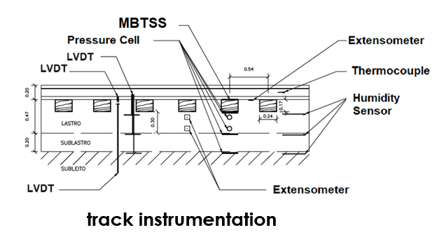
Test sites were instrumented with pressure cells, matrix-based tactile surface sensors (MBTSS), strain gauges, linear variable differential transformers (LVDTs), as well as temperature and humidity sensors. See Figure 3 for a diagram of the sensor layout at each test site.
Rail Pads
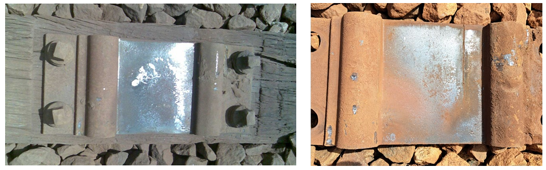
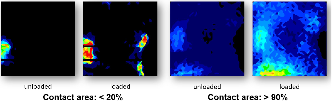
One of MRS primary goals for the project was minimizing rail breaks due to base fatigue—a type of failure that is associated with stress concentration on wood-tie tie plates, particularly near bridges and tunnels, Merheb said. “This type of rail break made up nearly 50% of MRS’ mainline brakes, at the time.” To remedy this, MRS worked with Getzner to develop a thin tie-plate pad designed to better distribute the load between the rail and the tie plate on timber ties (see Figure 4). Their test-site measurements showed that without the pad, the loaded rail/tie plate contact area was, on average, less than 20%. Once the pads were installed, the loaded contact area was, on average, greater than 90% (see figure 5). Based on these results, MRS widely deployed the technology at sites considered to be at elevated risk for rail-base-fatigue breaks.
The pads worked. MRS saw a 99% reduction in rail base breaks in locations at which the elastic tie-plate pads were installed, Merheb said. After nine years in service, or roughly 1,500 MGT, MRS removed several pads for analysis, wherein they determined that resilience and elasticity of the in-service pads was virtually unchanged versus new pads. “Our immediate problem was solved,” he said.
However, MRS was already in the process of replacing wood ties with concrete ties throughout the system. “Looking forward, the question was how to implement concrete ties without compromising the life cycle of the system,” Merheb said. Concrete ties offer many benefits, such as uniformity and quality control, durability and weight. They pose challenges, too, primarily in the tie/rail contact area due to rail seat abrasion, and poor (compared to wood) tie/ballast contact.
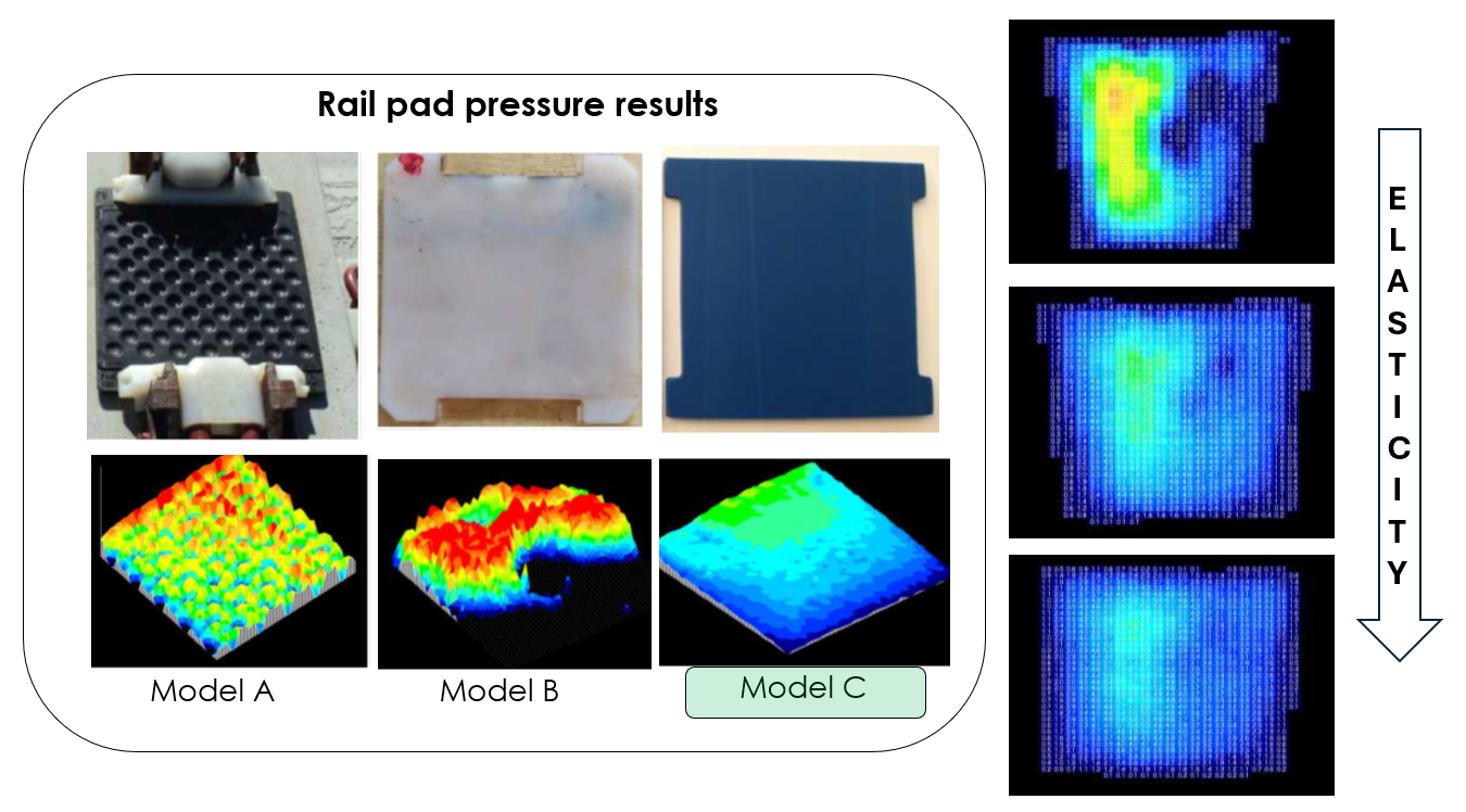
With this in mind, MRS spent three years (2014-2017) testing multiple rail pads and under-tie pads (UTPs). “We tested rail pads with different levels of elasticity to find the best solution for our specific conditions,” Merheb said. Figure 6 shows some examples of rail pads MRS tested, including loaded-pressure-map and elasticity data. They selected a rail pad that they considered to be ideal (with an estimated service life of 12 to 15 years, based on their track conditions and tonnage), then moved on to the next dilemma.
Under-Tie Pads
Tie/ballast contact and stress under load is neither uniform across the tie nor evenly-distributed into the ballast and sub-ballast, Merheb said. “There are ways to improve but not to “solve” these conditions.” Most “solutions” have significant tradeoffs. Increasing the size of the tie distributes loads more broadly, but greatly increases the weight of the tie, making maintenance more onerous. Small ballast gradations improve tie/ballast contact, but compromise drainage and ballast interlock. More frequent tamping can maintain more optimal tie/ballast contact, but frequent tamping reduces ballast’s service life and increases maintenance costs. Aside from an up-front cost, under-tie pads have no compromise, Merheb said. “They ensure a uniform tie/ballast interface and improve track resilience.”

MRS tested the tie/ballast contact area for several configurations—wood ties, steel ties, polymer ties, concrete ties, and concrete ties with UTPs. The results (shown in Figure 7) indicated that concrete ties without UTPs had a contact distribution area ranging from 22% to 32%. Concrete ties with UTPs had a contact distribution area ranging from 57% to 64%—better even than wood ties. MRS also measured the average pressure at the highest-load-bearing area at the underside of the tie beneath the rail. They found that UTPs reduced average pressure at the tie base from 1.1 MPa to 0.5 MPa—a ≈50% reduction.
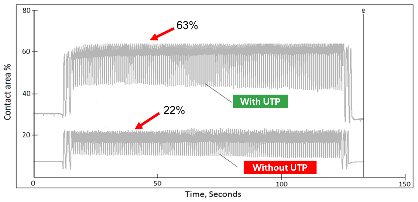
MRS also measured the tie/ballast contact area over time beneath a loaded train. This data (shown in Figure 8) showed that under peak loads, concrete ties with UTPs consistently achieved contact area percentages of 60% (peaking at 63%). Concrete ties without UTPs consistently achieved contact area percentages of <20% (peaking at 22%).
Naturally, changes in the tie/ballast contact area and pressure don’t only affect the tie, they affect the ballast, too. Tests conducted by MRS determined that without UTPs, the average pressure distribution between the tie and ballast ranged from 150 to 230 PSI. For ties with UTPs, the values were 60 to 90 PSI. “We also found a nearly 5x reduction in peak pressures,” Merheb said. “And high peak pressures are what really destroy the ballast quickly.”
Results and The Way Forward
As MRS’ track renewal program has progressed and more concrete ties with rail pads and under-tie pads have been deployed, the benefits are already clear and quantifiable. The charts in Figure 9, for example, show tamping cycles (time between required tamping) for different tie configurations. At MRS, tamping cycles are based on track geometry data, which is collected on a weekly basis to determine the rate of track degradation and when tamping intervention is required.
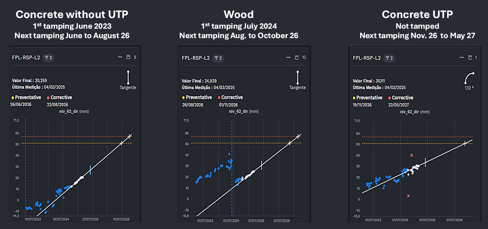
The chart on the far right of Figure 9 shows track geometry degradation for concrete ties equipped with UTPs. The shallow slope of the line in the chart (compared to the charts to the left) indicates a reduced rate of degradation. “Compared to concrete ties without UTPs, concrete ties with UTPs extend tamping intervals by a factor of three,” Merheb said. In other words, concrete ties with UTPs preserve track geometry such that tamping is required ≈3x less frequently.
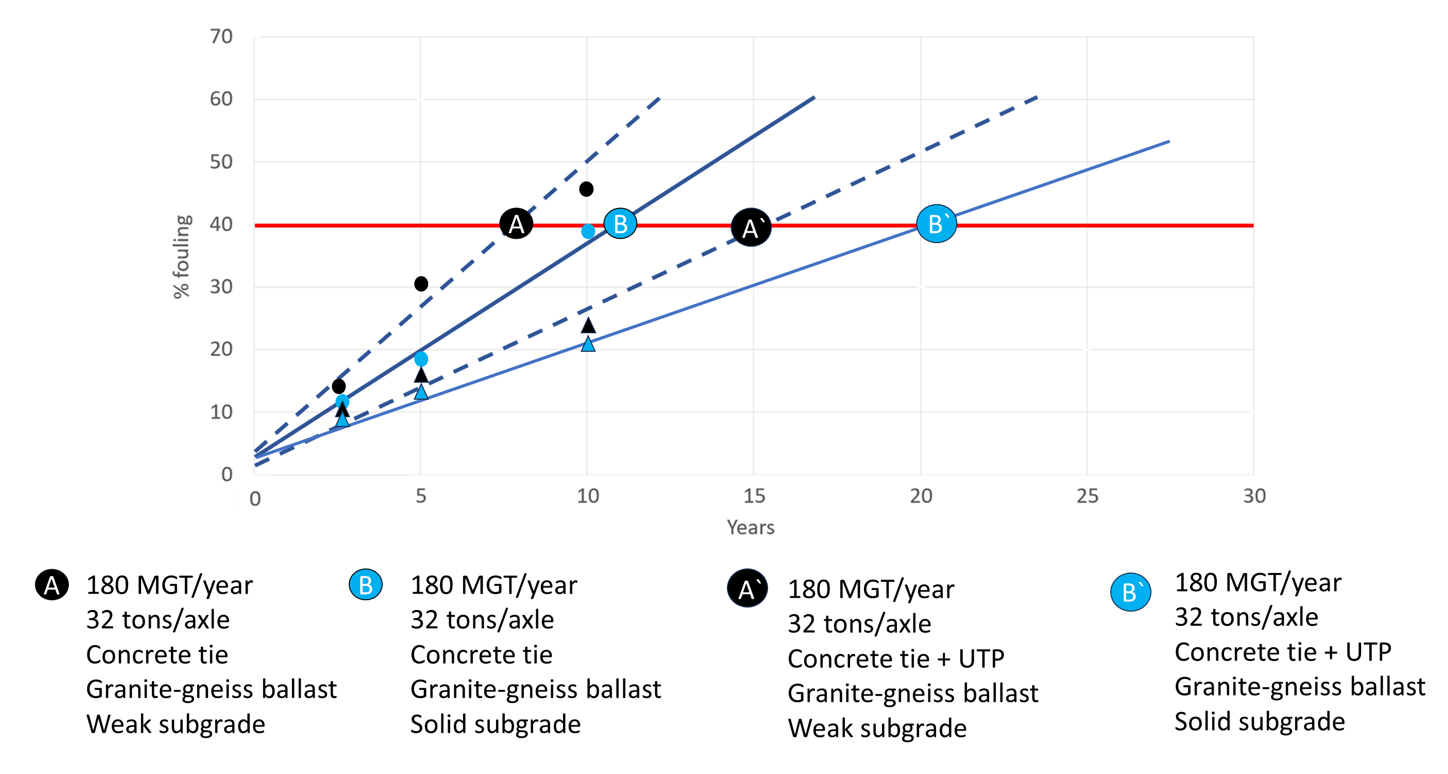
Sections of track equipped with UTPs have also seen a reduction in the rate of ballast degradation/fouling. Figure 10 shows ballast fouling rates based on 10 years of data collected from MRS test sites. The data shows that regardless of subgrade quality, UTPs reduce fouling rates (and thus ballast cleaning/undercutting) by at least a factor of 1.6, depending on MGT/year and subgrade quality, Merheb said.
All these benefits translate to significant economic gains. “Every dollar we put into the UTP program in the beginning has come back threefold in the span of three to eight years,” Merheb said (again, depending on factors such as traffic and tonnage, curvature, track condition, etc.). In addition to the benefits MRS has already quantified, the railway is also now studying the effects of rail pads and UTPs on the lifespan of other track components. MRS also intends to explore whether the use of UTPs could enable a reduction of ballast granular layer thickness or the use of lower-grade ballast without compromising performance—either of which would yield additional cost savings.
Track modulus, resilience, elasticity: these can seem like abstract concepts—the domain of theory rather than praxis. But there’s nothing abstract about the studies MRS has conducted, the practical applications they’ve demonstrated, or the benefits they’ve accrued. It’s a good reminder to pay attention to what’s going on beneath the wheel/rail interface.

Jeff Tuzik is Managing Editor of Interface Journal
This article is based on a presentation made at the 2025 Wheel/Rail Interaction Heavy Haul Conference.
All images are courtesy of Antonio Merheb and MRS Logística except where otherwise noted.