Applying Quality Concepts to the Wheel/Rail Interface (Part 1 of 3)
By Stephen S. Woody • October, 2007
Quality concepts have been used in various industries for many years to improve productivity, reduce expenses, and eliminate defects. Work done by the Norfolk Southern Research and Tests Department has begun to show that applying quality concepts to wheel/rail interaction can lead to significant operational and financial improvements.
In 2003, Norfolk Southern initiated a six-sigma project to improve the efficiency of the grinding program. Specifically, the project set out to determine how efficiently and howeffectively NS was grinding rail. Efficiency deals with the cost; effectiveness deals with the performance of the finished rail. You can grind very efficiently using only one pass, but you may leave profiles that cause the rail to fatigue prematurely or cause high lateral forces that contribute to fastener and tie degradation.
NS made two fundamental assumptions at the start of this project:
• The first assumption was that rail grinding is a “cost of poor quality.” It is considered as such because rail grinding is just artificial wear that shortens the life of the rail. The cost of poor quality associated with rail grinding is still much less than the cost of poor quality associated with allowing the rail life to be shortened by the formation of an excessive number of fatigue defects. So grinding is essentially the lesser of the two evils. In a perfect world, the railroad industry would be able to move freight without causing the rail to fatigue or wear.
• The second assumption was that longitudinal creep forces are the primary driver of fatigue damage and rail failures. These creep forces generate residual longitudinal tensile stresses in the head of the rail and allow fast fracture to initiate from smaller crack sizes. NS decided to reduce these forces and obtain the best steering without undue contact stresses by grinding the rail to a conformal profile.
As with any six-sigma project, NS began by collecting data. It created a set of codes to note the reasons why any curve or tangent received more than one grinding pass. As Figure 1 indicates, the “high” field side of the low rail accounted for 63% of the segments receiving multiple passes. An additional 11% of the segments exhibited a combination of “high” field corner on the low rail and rolling contact fatigue on the surface of the rails. Overall, high field conditions on the low rail accounted for almost 75% of the reasons for performing multiple grinding passes on a segment.
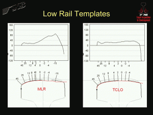
Having identified field relief of the low rail in curves as the primary reason for multiple passes, NS overlaid its low rail template on a typical low rail profile and determined that the template was the problem. The left side of Figure 2 shows the template overlaid on a typical profile. In order to match the profile to the template, NS needed to remove more than 0.080 inches in depth at one point. The extended horizontal line on the field side of the template promoted aggressive low rail field relief in order to prevent rail rollover derailments. This feature of the template drove the multiple passes associated with a “high” field condition discussed in the previous paragraph. The aggressive low rail field relief also biased the low rail contact toward the gauge shoulder, which caused wheelset steering problems.
The right side of Figure 2 illustrates the same profile with a low rail template developed by the Transportation Technology Center, Inc. (TTCI) using Wheel/Rail Tolerance (WRTOL) software. In order to design this new template, NS collected Miniprof measurements of wheel profiles from more than 100 representative wheelsets for this particular route. The TTCI imported these profiles into the WRTOL software, analyzed the contact points and rolling radii differentials, and designed a low rail template that provided conformal contact. With this new template, the maximum required depth of metal removal is less than half of that required with the original template. The new template moved the low rail contact point to the center of the low rail and restored proper wheelset steering.
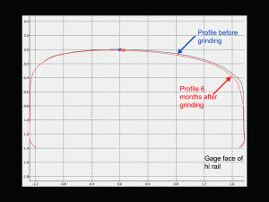
NS monitored the rail profiles at several sites of a test route during the six-sigma project. During one six-month period, the gauge corner of several new high rails wore heavily, particularly in the first two months following grinding (see Figure 3 for an example). Using the new low rail template and pre-inspection, NS was able to create conformal contact for 78% of the typical wheelsets at this site. However, within two months, only 50% of the wheelsets had conformal contact; and within six months, only 28% of the wheelsets had conformal contact.
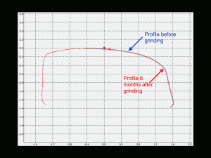
During the same six-month period, NS observed very little wear on an 18-year-old high rail with similar curvature at a different location (see Figure 4). This rail profile never produced conformal contact with more than 10% of the typical wheelsets. The high gauge-face angle on this rail caused heavy two-point contact, however, which generates poor steering and high lateral forces and caused tie plate cutting and loose spikes. Grinding cannot eliminate this problem. It can only be addressed by preventing the formation of the gauge face angle on new rail, by transposing an older rail, or by implementing top-of-rail lubrication to limit the creep forces.
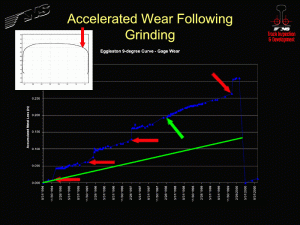
Based on this information, NS reviewed data that had been collected on a different coal route as part of a lubrication study. Figure 5 shows the metal loss in the high rail gauge shoulder over time. The arrows indicate each time that this rail was ground. The red arrows indicate that the rail was ground in a corrective mode. The Figure shows a dramatic jump in wear immediately after each grind, followed by a return to a steady-state wear rate after a short period of time. The green arrow indicates a grind in which the contractor was directed to limit metal removal in the gauge shoulder to 0.010 inches of depth. There was no jump in wear after this grind. If NS had been able to prevent the rapid wear that followed the corrective grinds, the rail would have had only about half of the total accumulated metal loss that it had when it was removed from service. NS determined that it was removing too much metal using corrective grinding and was, in fact, removing the work-hardened layer of the rail. As a result, the as-ground profiles were not stable.
In 2006, NS set out to stabilize the rail profiles on the system. It started by prioritizing selected routes and determined a time-based grinding frequency based on prior experience. It also began using a rail profile measuring system to perform pre-grind inspections and to automatically select the grinding pattern that would provide the best finished profile that would maintain the rail’s work-hardened layer. As the profiles have begun to stabilize, NS has begun to evaluate the finished grind quality indices as a measure of determining the appropriate grinding frequency.
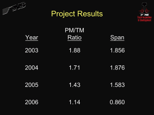
Figure 6 indicates that the mean pass mile (PM) to track mile (TM) has declined since NS initiated the six sigma project.
The decrease between 2004 and 2005 was due to the introduction of a new low rail template. The reduction between 2005 and 2006 was due to the introduction of a profile stabilization program. The span — a measure of how much variation there is in the process — dramatically declined last year in response to the stabilization program. While NS is now grinding efficiently, it still must ensure that the finished rail profiles provide the best operating conditions.
![]()
Stephen S. Woody is Manager, Track Inspection & Development, Norfolk Southern


