Vehicle Side Bearings: Function, Performance and Maintenance (Part 2 of 2)
By Gary Wolf • May 04, 2005
Part 1 of this two-part article explored the importance of roller style side bearings in maintaining proper vehicle performance and how improper maintenance of side bearings can directly affect wheel/rail forces. Part 2 examines the purpose, types of designs and maintenance of the constant contact, or resilient, side bearing
The use of constant contact side bearings came into prominence in the 1960s to inhibit the tendency of trucks/bogies to hunt at high speeds. The constant contact side bearing (CCSB), which, as the name indicates, is designed with no clearance between the car body and the bearing itself, prevents truck hunting by developing a small amount of turning restraint at the interface of the truck bolster and the car body. During truck hunting, the bolster rotates as the wheelsets move laterally back and forth between the rails. This small rotation occurs rapidly at a frequency between 1 – 3 Hz. Early CCSB designs used a metal spring to provide a small amount of compressive force upward against the side bearing wear plate.
The A. Stucki Co. pioneered the use of elastomeric elements that could be retrofitted in the standard roller cages. The elastomeric blocks functioned much like a rubber spring and provided several thousand pounds of compressive force against the wear plate (see Figure 1). As the truck bolster tried to rotate, or yaw, at high speed, the friction pressure of the elastomeric block against the wear plate resisted rotation or yawing. This inhibited the hunting tendency. The elastomeric blocks were relatively inexpensive and could be easily retrofitted in a standard side bearing cage, thereby increasing the high speed stability of a car without expensive modifications. Figure 2 shows a typical CCSB installation.
More cars were fitted with CCSBs during the 1970s and 1980s. The rise in intermodal traffic and the need for higher speeds was a driving factor. The development of Doublestack cars in the 1980s brought on new challenges. With shared articulated trucks, four side bearings were located on each bolster, instead of two. This increased the turning resistance of the truck during curving, which, under the right conditions, could increase derailment tendency. The situation was aggravated by the fact that one side (male) of the connector tended to wear faster, closing up the setup height faster.
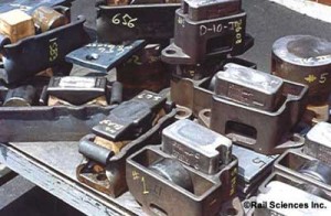
Designers went back to the drawing board and developed long-travel, metal-capped, and roller-assist CCSB designs. These new concepts largely mitigated the problem and are now commonplace on Doublestack and intermodal equipment (see Figure 3).
How CCSBs Work
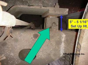
The theory behind the CCSB is fairly simple. To prevent a truck/bogie bolster from hunting, a small amount of restraint is necessary between the bolster and car body. Placing a compressed “spring” (either metal or elastomeric) between the bolster and the car body creates such a restraining force. By limiting the upward force against the wear plate to 3,000 – 4,000 pounds, the necessary restraint against hunting is developed. However, when the bogie bolster needs to rotate through a large angle while curving, the large steering forces of the wheelset will “break” the frictional force at the top of the side bearing, and allow it to freely rotate. To establish the correct amount of frictional force, the CCSB element is designed around the clearance envelope of a conventional roller side bearing design. With a conventional roller side bearing, the nominal clearance from the top surface of the bolster to the side bearing wear plate is 5-1/16 inches in order to provide for 1/4-inch clearance above the top of the roller. The CCSB manufacturers decided to work with this dimension and design the metal spring or elastomeric spring around it. Thus, when the setup height between the top surface of the truck bolster and the wear plate is 5-1/16 inches, the correct amount of pre-load on the wear plate will be developed when the elastomeric block is placed in the side bearing cage.
When Wear Takes Place
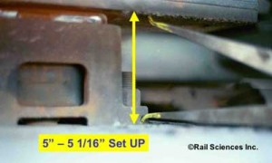
As you might expect, wear takes place over time and closes up the setup height from 5-1/16 inches to less than 5 inches. The primary source of wear is the combined wear on the surface of the body centerplate and the wear in the centerbowl. The AAR allows a nominal 5/16 inches vertical wear in the centerbowl (Rule 47). Also, a minimum of 1/16-inch clearance must be maintained between the bowl rim and the centerplate base. Over time, the body centerplate gradually sits deeper and deeper into the bowl, effectively closing up the clearance between the bolster top surface and the side bearing wear plate. The effect of this wear is to cause the elastomeric element, or spring, to shorten, or become more compressed. The more compression on a spring, the more force is developed within the spring. As the CCSB setup height is reduced below 5 inches, more and more frictional force is developed at the top of the elastomeric block and the wear plate. This frictional force resists turning of the truck bolster and in severe conditions can lead to a stiff truck condition. A stiff truck can lead to gauge-spreading forces under loaded cars, and wheel climb on empty cars. Maintenance of the correct setup height is important, or derailment can occur. Figure 4. shows the setup height being measured with a set of calipers. Alternately, go/no-go gages are available for a quick check on condemning limits.
In the early days, and before the critical importance of setup height was understood, many derailments occurred on long intermodal flats and autorack cars due to tight CCSBs. The long (66-foot) truck center length and stiff turning resistance was a two-fold problem. When encountering track twist, the vertical wheel load would be reduced, while at the same time, the lateral wheel force would be high due to turning resistance. The vertical force would go down while the lateral force went up. This combination would cause a high L/V ratio.
Another problem with certain CCSB designs was abrasion wear on the elastomeric blocks. After considerable service, the CCSB blocks tended to crack and abrade on the top surface. This caused the blocks to be ineffective in preventing truck hunting. As you might expect, the more the trucks hunted, the worse the wear became, and the blocks would quickly deteriorate once they started cracking. Also, operation in cold weather could exacerbate this problem, as the blocks became more brittle in sub-zero weather. When the blocks start cracking, irregular surfaces change the frictional characteristic of the blocks. Figure 5 shows cracks forming in the top surface of an elastomeric block.
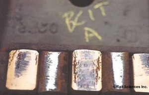
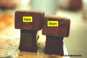
After considerable service life, the elastomeric material can take a permanent “set,” resulting in loss of preload on the wear plate, and an attendant loss of hunting restraint. Figure 6. shows a comparison of a new metal-capped side bearing with a service worn side bearing exhibiting a permanent set.
Metal Capped CCSBs
To overcome the wear problem with the elastomeric blocks, and to provide a more consistent frictional force on the top surface, metal-capped CCSBs were introduced in the late 1980s. Both the A. Stucki Co. and Miner Enterprises, Inc., developed CCSB designs using a metal cap on top of elastomeric blocks. Stucki introduced designs with a removable metal cap that could be inserted into special indents in the top of the elastomeric blocks. Miner Enterprises introduced TCC designs using a metal cap that was directly bonded on the top of the TecsPak® elastomeric material. Most of the A. Stucki designs could be retrofitted into conventional roller side bearing cages, whereas the Miner design used a proprietary cage unique to their cap design.
Other metal cap designs were developed including roller assist designs. In the roller assist design, a standard steel roller is placed beside the elastomeric element to assist in curving when excessive preload is developed during car leaning in curves.
Maintenance of Constant Contact Designs
Until several years ago, the AAR interchange rules referred to “the manufacturers’ specifications” when it came to maintenance and inspection of constant contact designs. Now, the new Rule 62 states specific guidelines for the maintenance of constant contact designs. Several important provisions of Rule 62 are:
Wear limits, Gaging and Cause for Renewal or Attention:
• Heat damaged or missing elastomer elements.
• Broken or split elastomer elements if exhibiting two or more vertical cracks each greater than 1/2 inch in length.
• Metal caps worn through wear limit indicators, where such indicators exist.
• Repair is required at anytime where height measured is:
– Less than 4-7/8 inches
– Greater than 5-1/4 inches
The reader should consult AAR Rule 62 for other important inspection, measurement and maintenance provisions for both constant contact and conventional roller designs. In addition, both the A. Stucki Co. and Miner Enterprises have produced handy “pocket guides” for identification and maintenance of their respective designs. It is important to remember that the setup height should be closely maintained to the AAR and manufacturer’s specifications in order to prevent the development of excessive turning moments during vehicle curving. Cars with setup heights below 4-7/8 inches can contribute to derailments due to rail rollover or wheel climb. If elastomer elements are missing, split, broken or cracked, they may not be effective in preventing truck hunting, which could lead to high-speed derailment. Either way, the CCSB setup heights should be inspected and closely monitored to ensure proper vehicle performance and reduce the risk of derailments.


