
Truck Warp: Causes and Cures (Part 2 of 2)
By Gary P. Wolf • November 1, 2004
Part 1 of Truck Warp: Causes and Cures covered the three primary causes of truck warp:
- An insufficient longitudinal steering moment is developed at the wheelset due to poor profile characteristics, typically, hollow-worn wheels.
- An insufficient warp stiffness or moment is present at the bolster-to-sideframe interface, otherwise known as the friction castings, or friction wedges. Or, an insufficient stiffness is present at the wheelset bearing adapter-to-sideframe interface.
- A significant resistance to bolster rotation, or turning moment, is developed due to friction in the centerbowl, or rotational resistance due to tight side bearings.
Part 2 of this article explores these causes in more detail and, more importantly, what can be done to prevent trucks from warping.
Lack of sufficient steering moment
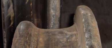
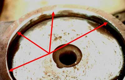
Hollow-worn wheels are the primary reason that wheelsets fail to develop sufficient steering force to steer the bolster and truck through curves. For many years, the industry lacked a hollow wear standard in the AAR Field Manual. (Figure 1 shows an extremely hollow-worn wheel that was found running in the North American fleet.) Typically, hollow-worn wheels are changed out due to a high flange, a vertical flange, or excessive tread wear. In mid 2004, however, a new hollow wear standard was inserted into AAR Rule 41, and a new gauge was designed to check for hollow wear. The current hollow wear standard allows up to 4 mm of tread hollow before the wheel is condemnable.
In addition to poor steering, hollow wheels also create excessive contact stresses on the rail that can lead to head checking or shelling of the high rail and surface spalling of the low rail in curves. Hollow-worn wheels also cause trucks to hunt at less than normal critical speeds. Any way you slice it, excessively hollow-worn wheels increase the stresses and forces that are transferred to the track structure. Some railroads – especially captive heavy-haul systems – have recognized the poor characteristics of hollow wheels and change or re-profile wheels at approximately 2 mm of tread hollow. They have found that this practice actually lengthens the life of the wheelset and the rail.
Poor rail maintenance practices can also cause poor steering conditions. Railroads that excessively grind the gauge corner of the high rail of curves, for example, can create two-point contact, which inhibits wheelset steering. Similarly, failure to relieve the profile build-up on the field side of the low rail can result in poor wheelset steering. Finally, excessive negative rail cant can reduce the effective steering of the wheelset.
Insufficient Warp Stiffness
The friction casting, or friction shoe, or friction wedge provides vertical damping as well as warp stiffness. The friction wedge rides in the bolster pocket with its back surface rubbing against the roof of the bolster pocket and its front surface rubbing against the column wear plate. A large control spring under the friction wedge pushes the wedge up into the pocket, with a resulting friction force developed against the column wear plate. It is this friction force that dampens out road shocks and resists the tendency of the bolster to warp, or lose its 90-degree alignment with the side frame. There are two primary types of trucks used in North America: the constant-damped truck, typically called the Ride Control Design; and the variable-damped truck, typically called the Barber Design.
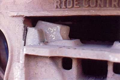
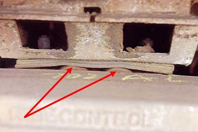
After many miles of operation, the constant frictional rubbing of the friction wedge against the pocket and column wear plate creates wear on the steel surfaces. The result of this wear is that the bolster pocket gets larger, the column wear plate wears deeper into the side frame and the friction wedge itself gets smaller in dimension. The net result of wear on these three surfaces is that the friction wedge rises higher in the pocket, pushed upward continually by the control spring force. As the control spring expands to push the wedge higher into the pocket, the force on the spring diminishes, resulting in less friction, and inevitably, less damping and warp stiffness. This rise of the friction casting above the top of the bolster is termed “wedge rise.” (Figure 2 shows an example of a ride control truck with extreme wedge rise of nearly 3 inches.)
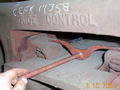
Each truck manufacturer specifies the maximum amount of wedge rise permissible. Generally, most Barber designs can tolerate an approximately 3/4 inch wedge rise before the truck loses its damping and warp stiffness. By contrast, most Ride Control designs can tolerate approximately 1-3/4 inches of wedge rise. (Other truck designs such as National and Buckeye have other criteria for evaluating the loss of truck damping.) While wedge rise condemning limits apply when a car is being re-built to AAR Rule 88 standards, there currently is no AAR interchange standard for condemning a truck for wedge rise when it is on the rip track for maintenance. Some railroads recognize the importance of wedge rise and maintain their own fleets to the manufacturer’s standards. (Figure 3 shows the use of the “moustache” gauge to check for excessive wedge rise.)
Excessive Truck Turning Moment or Bolster Rotational Resistance
A truck or bogie should be free to turn or steer on the car body center casting as it negotiates curvature. Conditions between the car body centerplate and the bolster bowl can inhibit free steering of the bolster. First, we need to recognize that the centerplate is actually a center “bearing.” With any bearing, lubrication is essential. AAR Rule 47 specifies that the center casting should be lubricated or an approved centerbowl liner should be used whenever the car body is raised for maintenance. Tests have shown that many of the plastic style liners can maintain their lubrication effectiveness longer than conventional greases.
Another common cause of excessive friction at the centerplate is contact, or fouling, between the centerbowl rim and body centerplate. AAR Rule 47 specifies that a minimum clearance of 1/16-inch should be maintained between the centerbowl rim and body center casting. Excessive friction or rubbing on the bowl rim will cause resistance to turning, or worst case, can tend to lock up the bolster from turning. (Figure 4 shows evidence of a center casting rubbing on the bowl rim.) Center casting fasteners such as huck bolts that rub on the side of the bowl rim also can inhibit bolster steering.
Finally, tight side bearings can cause resistance to bolster rotation. AAR Rule 60 specifies that a clearance of 3/16 to 5/16 inches should be maintained at each conventional side bearing location. The clearance should be checked for proper dimension on both conventional roller or steel block side bearings, and the set-up height on constant contact designs.
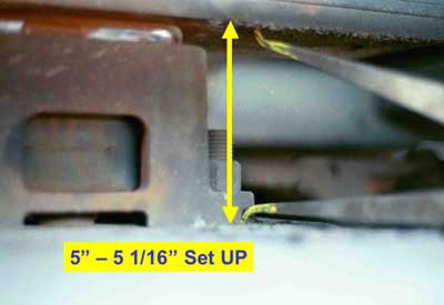
(Figure 5 shows an example of a conventional roller side bearing with insufficient clearance.) AAR Rule 60 also specifies that a minimum set-up height of 4-7/8 inches should be maintained for constant contact designs. Manufacturers have traditionally recommended a minimum set-up height of 5 inches. Go/no-go gauges, or calipers, can be used to check set-up heights. Failure to maintain proper dimensions will result in added resistance to turning and the potential to cause truck warp.
(Figure 6 shows an example of a constant contact side bearing measured with calipers.)
Truck warp has been shown to cause excessive gauge-widening forces, which increase wheel, rail and fastener wear, and tie degradation. At worst, truck warp can result in rail rollover or gauge spreading. The root cause of most truck warp lies in excessive wear of truck components, or failure to maintain proper clearances as the truck wears. Knowledge of the causes of truck warp and attention to inspection and maintenance procedures can help reduce its negative effects on vehicle and track components and operating conditions.
