Rock ’til You Drop: Starting and Stopping Harmonic Rock and Roll
By Gary Wolf • February 1, 2005
It’s said that “it takes two to tango,” but it takes three critical elements to induce harmonic rock and roll:
- An operating speed between approximately 12 and 24 mph.
- A vehicle conducive to rocking due to its mass and spring characteristics.
- A series of vertical track perturbations that are severe enough to excite the vehicle.
Like many of the other legendary “rockers,” freight car rock and roll came to the forefront in the ‘70s. The introduction of high-center-of-gravity, 100-ton hopper cars operating on jointed track caused a dramatic increase in the number of derailments attributed to the phenomenon of harmonic rock and roll. The problem was met head on with a number of industry research initiatives that clearly defined the problem and potential solutions. Even with those solutions, however, a number of derailments are attributed each year to harmonic rock off (FRA code M405). More than 260 reportable derailments were caused by harmonic rock off in the U.S. over the past three and a half years.
Any mechanical system comprised of springs will vibrate or resonate at a given natural frequency, know as its harmonic frequency, when excited. A good example of a simple harmonic system is a guitar string. Depending on the mass (weight/diameter) of the string, its tightness (spring constant), and location of striking, the string will resonate with a certain tone or frequency. A freight car is also a harmonic system comprised of mass and springs with a critical frequency at which it tends to resonate. For a typical freight car, the resonant frequency occurs at between 12 and 24 mph.
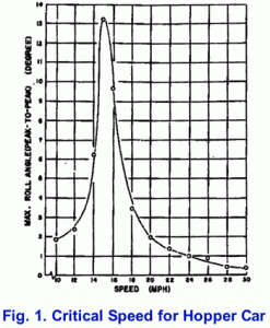
The energy required to excite car rocking comes from the track structure, principally the pattern of joint spacing. Joints tend to deflect vertically under the weight of the wheel, allowing the springs to compress in response to the joints. The energy stored in the compressed springs is then fed back into the car body between the joints, propelling it in the opposite direction. If the joints are staggered at approximately one-half rail length apart, the maximum energy is fed into the car body at just the precise frequency to violently rock the car back and forth, from side to side. In extreme conditions, wheel lift and derailment can occur. The forward speed of the car, in conjunction with the joint deflection and spacing, determines the exciting frequency. The spring characteristics, center of gravity height, and truck center distance determine the resonant frequency of the freight car. Therefore, operating at the resonant speed over jointed track has the potential to excite a car into its natural rocking mode. Figure 1 shows the harmonic response curve of a typical hopper car.
Track Factors
Rock and roll occurs primarily on track with staggered joints. The FRA defines staggered joints as joints that alternate left and right and are spaced more than 10 feet apart. Many railroads’ past practice was to stagger the joints exactly one-half rail length (19.5 feet) apart. While this practice had merit in the early days of railroading, the advent of 100-ton hopper cars with nominally 39- to 40-foot truck center spacing caused severe harmonic rocking when operating over half staggered joints. Many railroads changed their practices to break this pattern and began to stagger joints at one-quarter to one-third rail length apart. This corrective action had good success in eliminating rock and roll. Another corrective action used by some railroads was to install longer 78-foot, jointed rail on one side of curves. This tended to break up the harmonic action by eliminating every other joint.
Simply operating a car over staggered joints does not automatically ensure that it will rock and roll violently. There must be sufficient vertical deflection at the joint to introduce sufficient energy into the car body to excite the rocking motion. In general, a dynamic joint deflection of more than 1 inch is required to begin significant rocking motion. Joints that deflect due to poor tie, ballast or pumping conditions are candidates to excite harmonic rocking. There also must be a number of consecutive joints, generally five or six in a row, to sustain the rocking motion. Maintaining track to FRA standards should prevent most rock and roll derailments. In addition to the well-known track geometry standards, the FRA made an important addition in 1999. FRA CFR49 213.63 states: “…to control harmonics on Class 2 through 5 jointed track with staggered joint, the crosslevel differences shall not exceed 1-1/4″ in all of six consecutive pairs of joints, as created by 7 low joints…”
Car and Vehicle Factors
Freight cars are not created equal when it comes to harmonic rocking. Certain characteristics make some cars more susceptible to rocking. The principle factors in determining the probability of severe rocking are:
- Vehicle truck center distance and weight of car.
- Vehicle center-of-gravity height above rail.
- Spring constant or stiffness.
- Type and amount of damping in the suspension system.
- Amount of side bearing clearance.
Freight car geometry is generally fixed, depending on the car design and purpose. As stated, when the truck center distance is close to the rail joint spacing (39 feet, nominal), rocking becomes more severe. Thus, longer cars, and cars with articulated joints are not as susceptible to harmonic rocking. When the center of gravity exceeds 90 inches, the severity of rocking is increased. Hopper cars tend to have higher CG heights due to the voids formed by the slope sheets.
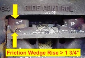
Suspension stiffness and damping are critical factors in determining susceptibility to rocking. While spring stiffness is nominally fixed, depending on the car weight and dimensions, damping levels can vary considerably, depending on the wear in the suspension system. Previous Interface Journal articles have addressed the importance of suspension damping and wedge rise. As wear occurs on the damping elements, the ability of the suspension to dampen out the unwanted rocking motion is severely compromised. Thus, wedge rise should be maintained to manufacturer’s specification in order to control or prevent excessive rocking. Figure 2 shows a truck with excessive wedge rise.
Some cars require supplemental hydraulic damping to pass the AAR car stability acceptance criteria (M965). In these cases, it’s incumbent upon maintenance personnel to ensure the effectiveness of the hydraulic damping system by checking the level of oil in the sight glass or by looking for signs of leakage.
Side bearing clearance for standard roller side bearings should be maintained between 3/16 and 5/16 inches. Excessive side bearing clearance is a prime contributor to the severity of car rocking. Side bearing clearance in the range of 1/2 inch will allow the car to lean or roll to excessive limits, which increases the energy input to the springs and car body.
Car Rocking Symptoms
When inspecting a freight car, there are several telltale signs that the car is a bad actor, with regard to harmonic rocking. The following components should be visually and dimensionally checked:
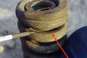
- Springs. Look for evidence that the springs are cracked or broken, or that they have compressed “solid.” Wear or shiny marks between the spring coils (see Figure 3) are evidence of solid springs.
- Friction Wedges or Friction Castings. Inspect the wedges for excessive rise above the top of bolster. On most Barber truck designs, wedge rise should not exceed nominally 3/4 inches. For most Ride Control designs, the wedge rise should not exceed nominally 1-3/4 inches. Also inspect the column wear plates for excessive wear or hollowing of the plate.
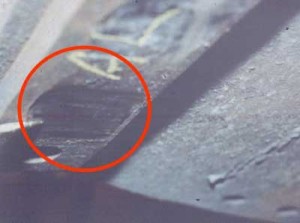
- Side Bearing Clearance and Wear Plates. Side bearing clearance should not exceed 5/16 inches, or excessive rocking will be allowed. Inspect the body wear plates for signs of cracking or excessive pounding. Sometimes the wear plates will be severely dished or hollowed from the repetitive pounding into the roller (see Figure 4).
- Centerplate Casting. The centerplate casting will show signs of cracking, particularly around the fillet area or along the relief area on the bottom of the centerplate.
Most rock and roll derailments are caused primarily by lack of damping in the car, or excessive side bearing clearance. For track to be a primary cause, the track structure must be severely deteriorated with a number of consecutive, staggered, pumping joints. To prevent rock off derailments, avoid operating trains in the critical speed range of 12 to 24 mph when handling loaded hopper cars over jointed rail. Heeding these operating precautions, maintaining the track joints and insuring proper damping in the car suspension can make harmonic rock and roll a thing of the past.


