Vehicle Side Bearings: Function, Performance and Maintenance (Part 1 of 2)
By Gary Wolf • April 04, 2005
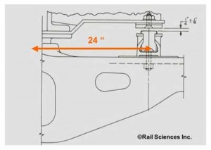
Side Bearings serve as support elements on the truck bolster and are located to the side of the centerplate. The function of the side bearing is to support the underside of the car body bolster in the event the car leans to one side or the other. When a car operates around a curve on superelevated track, the car body can lean to the outside of the curve if the car is traveling over balance speed; or it can lean to the inside of the curve if the car is traveling under balance speed. The car body, which is normally supported entirely by the 14- or 16-inch body centerplate, can tip or roll up on the outer edge of the body centerplate. If there were no additional means of support, the car body, in extreme cases, could tip on its side. The side bearing prevents an excessive amount of tipping by providing additional support at a location approximately 24 inches from the car center pin. Figure 1 shows a typical application and location of the side bearings on a truck bolster.
The modern side bearing consists of a hardened 3-inch steel roller placed into a steel cage, or box-like device. A single roller is used in 70-ton cars, two rollers are used in 100-ton cars. The steel cage is typically bolted to the truck bolster with two fasteners. There is adequate longitudinal clearance in the cage to allow the roller to move back and forth. Allowing the side bearing roller to move back and forth facilitates turning of the truck bolster on the car body during curving. A hardened flat steel plate is attached above the roller to the car body bolster. The roller rubs and bears against this flat steel plate. There is a gap on approximately 1/4-inch between the roller and the body wear plate (see Figure 2).
Side Bearing Clearance
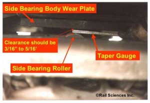
Normally there is a gap, or clearance of approximately 1/4 inch between the top of the side bearing roller and the car body wear plate. In fact, AAR interchange rules specify that the clearance gap should be no wider than 5/16 inches and no smaller than 3/16 inches. When traveling on level, tangent track there is no useful role for the side bearing. If the car encounters rough track and the car begins rolling side-to-side, contact will occur. Or if the car enters a curve and leans over, side bearing contact will occur. If the side bearing gap, or side bearing clearance, is too wide (>5/16 inches), it will allow excessive rolling or leaning of the car body. If the gap is closed up tighter than 3/16 inches, premature contact will occur during curving. Neither of these conditions is desirable. If side bearing clearance is too tight, two conditions can develop:
• The car will exhibit excessive resistance to curving.
• The car will not be able to accommodate normal track twist conditions without exhibiting an excessive amount of wheel unloading.
Both of these conditions can directly lead to a derailment. Any resistance to curving will cause higher than normal lateral force, with an attendant increase in L/V ratio (assuming the vertical force remains constant). Thus, cars with tight side bearings often cause wheel-climb or rail-rollover derailments. Heavy commodity cars with tight side bearings can generate large lateral forces due to truck warp. This in turn leads to high truckside L/V ratios and a tendency to roll rail or spread gauge. In addition, cars with tight side bearings will cause excessive wheel unloading, especially when negotiating curve spirals or low joints in the track. This can cause cars with long truck centers, or torsionally stiff cars such as empty tank cars, to climb the high rail of curves during curve entry or exit.
As the car encounters the entrance spiral, the bolster will start to rotate against the car body. If adequate clearance is present at the side bearing, there is no resistance to turning due to side bearing friction or slip-stick. As the car continues to enter the body of the curve, contact might occur at some point on the inside or outside side bearing. By this time, the bolster has likely rotated to its full position, and the effect of side bearing friction is minimal.
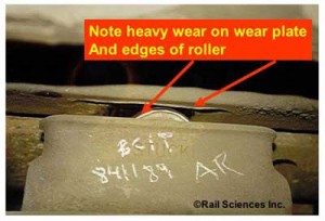
If side bearing clearance is tight as the car enters the spiral, even a small amount of leaning can take up the slight clearance, leading to friction on the top of the roller and the potential for slip-stick to occur. As the car moves deeper into the spiral, crosslevel differences increase the twist on the car and the resultant normal force on the side bearing. At this point, the potential for excessive turning resistance is increased to the point of causing a stiff truck condition. Thus, tight side bearing clearance is a prime cause of high lateral wheel forces due to truck turning resistance. Rail Sciences’ tests and inspections of freight cars developing high lateral forces, or cars with warped truck condition, have shown that tight side bearings were present in roughly 50% of the cars exhibiting curving problems. Figure 3 shows an example of a tight side bearing condition.
Tight Side Bearings and Track Twist
Track twist can occur during spiral entry or exit, where twist rates of 1 inch in 50 feet are common. Track twist can also occur due to low spots or low joints in the track. The FRA sets limits on the amount of allowable track twist over a 62-foot chord or length. For instance, in class 4 track, the maximum allowable track twist is 2 inches over 62 feet. The result of track twist is vertical unloading, particularly on the diagonally opposite end of a car. If you hold a shoe box in your hand, and push down on one corner, you will note a tendency for the opposite diagonal corner to raise up. If this were a freight car, the raising action would result in an undesirable loss of wheel load. If side bearing clearance is nominal (1/4-inch), cars can accommodate the prescribed amount of allowable twist without exhibiting an excessive amount of wheel unloading. With tight side bearings, however, the effect of track twist on wheel unloading is worsened.
When negotiating twist, the car body leans and the pressure on the edge of the centerplate is increased. However, since the centerplate is only 16 inches in diameter, the resulting roll moment effect on the truck bolster is minimal. If side bearing clearance is tight, the vertical roll moment is instantly transmitted to the top of the roller and into the truck bolster, resulting in a tight compression of the bolster springs on one side of the truck. This creates a significantly larger roll moment on the bolster due to the effect of a 24-inch moment arm acting at the side bearing location. When this occurs, wheel unloading on the opposite side occurs. Cars with normal side bearing clearance can accommodate up to 2 inches of twist across truck centers with a loss of only about 20% of the vertical wheel load. However, cars with tight side bearing clearance can lose more than 50% of the vertical wheel load while negotiating track with only 1 inch of twist across truck centers. Thus, cars with tight side bearings are prone to wheel lift and wheel-climb derailments even on track with FRA-compliant track twist conditions.
Cars with excessive side bearing clearance tend to rock and roll excessively, especially when operating in the critical harmonic speed zone of 15 to 25 mph. The roll angle will increase proportional to the amount of side bearing clearance above 5/16 inches. Side bearing clearance should be checked at each corner of the car using a taper gauge, shims or other device. Always measure side bearing clearance on level, tangent track. Measuring side bearing clearance on twisted or curved track usually results in erroneous data. Figure 4 shows the use of a taper gauge to check the clearance between the roller and body wear plate. Consult AAR Rule 62 for further information on side bearing standards and maintenance procedures.
Part 2 of “Vehicle Side Bearings: Function, Performance and Maintenance” will examine design features and maintenance issues associated with constant contact or resilient side bearings.


