What Kind of Rail Materials Will Survive in Heavy-Haul Service? (Part 1 of 2)
By James R. Hornaday, Jr.
In many ways, rail is the most important component in a railroad system. The economic value of installed rail is usually the most costly asset listed in any railroad’s financial accounts. The financial stability of a railroad is often determined by how well that installed rail holds up in service. If it wears out rapidly, or breaks unexpectedly, the railroad will lose its ability to deliver goods on time, and it will not be a profitable operation.
Currently, the best rail material for heavy-haul railroad service is high carbon, minimal alloy content steel, with a completely pearlitic microstructure. With the increasing demand for increasing car axle loads over the past several years, this type of rail steel has contained progressively higher carbon content and corresponding higher strength, which have provided better durability. Within the metallurgical and railroad communities, there is some thought that these progressive improvements in pearlitic rail steel may have reached full maturation, and that a completely different composition and structural rail material will have to be developed for future heavy-haul rail service.
One of the important engineering facts of life in heavy-haul rail service is that the contact stresses across the wheel/rail interface exceed the current wheel and rail yield stresses. Wheels and rails are continuously plastically deforming each other. A wheel rolling on a rail, even without traction forces, will generate compression overload stresses on both components, which will compression-deform the wheel and the rail surfaces. A wheel rolling on a rail with imposed traction forces will generate greater combined compression-shear overload stresses on the wheel/rail surfaces.
Pearlitic structure rail and wheel materials are the only known materials that can withstand the continuous overstressing that occurs in heavy-haul service. The maximum useful hardness of as-produced pearlitic steels in track service is probably 400 to 410 Brinell (Bhn). Pearlitic rail steel surface layers, when fully wheel-hardened, commonly achieve hardnesses approaching 500 Bhn. Even at this hardness, however, a rail steel’s enhanced yield strength still will not be high enough to resist further deformation under continued wheel loading.
There are many engineering materials that can demonstrate higher hardnesses and higher yield strengths than pearlitic steels. Quite a few of these presumed good candidate rail materials have been tried in track service. None have yet demonstrated good service lives. The reasons for their poor service capabilities have been numerous:
— The alternate rail materials may not have been capable of being welded into long CWR strings, or to be repair welded in track.
— The alternate rail materials exhibited accelerated surface spalling and/or surface corrugation defects.
— The alternate rail materials initiated too many shelling defects.
Understand how and why pearlitic rail steels survive longer than “other” materials in heavy-haul service requires recognition of three facts:
— Any stressed material element will initiate plastic deformation (or yield) when the applied stress exceeds its yield strength.
— Any stressed material being deformed by a continued stress overload will yield plastically without cracking when the material’s deformation capabilities are not exceeded.
— Any deformation stressed material that goes beyond its strain-limiting capabilities will initiate a micro-crack. Further stressing will quickly propagate that micro-crack into a finite size crack, ultimately developing into a surface corrugation crack, a surface spall defect, or, in an extreme case, a complete fracture of the rail.
Understanding how pearlitic steels somehow meet these overstress conditions and survive in heavy-haul service requires examination of an as-mill-formed pearlitic structure, and understanding of how pearlite in a rail head surface reacts to wheel overload.

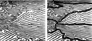
Figure 1. As-formed pearlite is mixture of alternating platelets of pure iron and iron carbide. The section plane photo images show their three-dimensional structure.
As-formed pearlite is mixture of alternating platelets of pure iron and iron carbide. The basic three-dimensional structure can be seen in Figure 1’s section plane photo images.
The primary left image shows several pearlite colonies (as defined by the imaginary heavy black lines in the right hand image) within a typical rail steel. Within each pearlite colony, there are reasonably parallel alternating layers of white ferrite and dark etching iron carbide. The ferrite is very soft and ductile. The thin iron carbide platelets are extremely hard and can be broken easily. The bond between the ferrite layers and the iron carbide platelets in the pearlite is quite good.
Hypoeutectoid rail steels containing less than 0.78% to 0.80% carbon contain colony-size patches of pure ferrite. These common previously used rail steels, with excess soft ferrite, did not exhibit composite hardnesses equal to rails with a completely pearlitic structure. Heavy-haul service has shown that hypoeutectoid rails are prone to accelerated plastic deformation of the rail head, and required frequent grinding to maintain proper rail head profiles throughout their short service lives.
Hypereutectoid rail steels with carbon content in the 0.80 to 0.82% range will contain some excess volume fraction of discrete equiaxed carbide particulate, rather than being consistently in the form of plate form particles. The intention in producing a good hypereutectoid rail material is to keep the excess carbide particulate as small as possible. The highest as-rolled hardness rails today are hypereutectoid carbon rails. While hypereutectoid rails are being used by most railroads and seem to be performing well, there is no universal agreement yet that hypereutectoid rail steel will be the all-around longest-life rail.
A second factor in determining the composite hardness of a pearlitic steel is the spacing between alternating layers of ferrite and pearlite. The hardest pearlite structures are formed by controlled accelerated cooling of a hot-rolled rail as it comes out of the final hot-rolling stand in the rail mill. Several rail mills commonly produce premium-quality rails, with maximum useful head hardnesses. It is likely that these mills’ head-hardening processes have reached their full capabilities. There might not be any significant improvements in railhead hardness by continued ‘tweaking’ of the hardening processes.
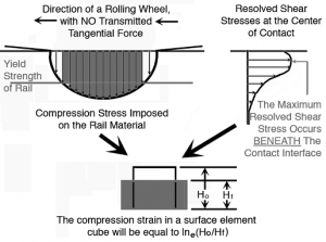
The stress vectors of wheels transmitted across a rail-wheel interfacial area can be quite different; a wheel exhibiting pure frictionless rolling will generate a simple compression overload stress on the rail. The compression deformation strain will flatten the rail surface in the interface, and will ultimately lead to observable change in rail profile. The maximum stress induced anywhere in the rail will be beneath the rail surface, as shown in Figure 2.
If the maximum subsurface resolved shear stress material contains a local material flaw or weakness, a subsurface crack will form. That crack, with passing wheels, will initiate a longitudinally oriented shell defect beneath the rail head surface.

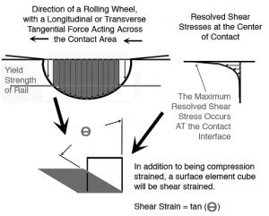
Figure 3. Any tangential force exerted across the wheel/rail interface by a rolling wheel will generate quite a different response in the rail.
Any tangential force exerted across the wheel/rail interface by a rolling wheel will generate quite a different response in the rail. This situation is schematically shown in Figure 3.
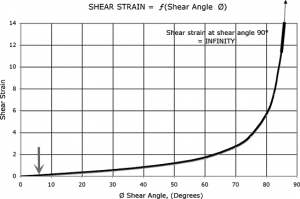
The simple formula for shear strain shown in Figure 3 does not readily indicate how much plastic deformation strain will be generated in a primary rail steel microcube element as a function of rotation angle theta. The relationship is graphically shown in Figure 4.
Proper quality rail steel, meeting current AREMA specification requirements for tensile ductility requirements, can be tensile strained 11% without breaking. The shear strain angle, equivalent to an 11% uniaxial tensile strain, (as shown by red arrow in Figure 4) is 6 degrees.
The relationship shown in Figure 4 is further illuminating in that as the plastic deformation strain produced by shear deformation approaches infinity as the theta angle approaches 90 degrees. In other words, the rail steel head surface structure that has demonstrated significant shear angle distortion has been strained beyond its nominal uniaxial tensile strain capabilities, and it can’t contain a stress-induced crack, or the rail will have initiated a spalling corrugation crack.

Figure 4. The relationship between shear strain (shown in Figure 3) and plastic deformation strain in a rail steel microcube element can be graphically shown.
Metallurgical examination of as-rolled rail, as shown previously in Figure 1, indicates several pertinent observations:
— Pearlitic colonies’ crystal orientations are randomly distributed.
— The iron carbide platelets within each colony are generally continuous and are not broken into small discrete aligned particles.
High magnification section examination of the near running head surface layer material of a worn rail indicates there are progressive changes in the rail’s pearlitic structure:
— The orientations of whole pearlite colonies are spontaneously and progressively changed. The iron carbide platelets become progressively aligned with the predominant direction of rail surface shear strain.
— The flat iron carbide platelets break up into small, aligned particles.
At 1000x magnification, the discernible rail material at the extreme running surface appears to be free ferrite and small carbide particles that are aligned in a direction approaching parallel to the extreme surface. In other words, the nominal shear deformation angle of all the running surface rail material is extremely close to 90 degrees. The combined plastic compression-shear deformation capability of pearlitic rail without initiating a surface crack is phenomenal.
This primary characteristic of pearlitic carbon low alloy rail steel that makes it superior to any current challenger rail material is that it can withstand tremendous amounts of combined compression-shear deformation overload before it initiates a surface spall crack. No other alternate rail material can do this without initiating spall cracks with lesser service exposure. On the other hand, there are reasons why pearlitic steel rail, with all its good characteristics, gives track workers fits and a desire for a better rail material
High carbon steels are all extremely notch sensitive. If there is any small flaw or weak spot in a pearlitic structure rail, it is subject to a sudden cleavage fracture with the application of, sometimes, minimal stress loading. Micro-cracks or flaws in rail will easily propagate into larger cracks with what would be considered entirely normal service stress loading. Once a crack or flaw is present in a rail, it will eventually grow in service to a size that makes it a candidate for sudden, brittle fracture. Flaws can be found anywhere in a rail section.
Rail Flaws Generated by Primary Mill Processing
Some flaws are original defects produced in the rail mill. A heavy-haul railroad’s procurement of rail with proper strength and produced by good “clean-steel” melting procedures is merely an assurance that the rail will not catastrophically fail within a short service period. Rail meeting heavy-haul service quality standards still contains small flaws that can grow to critical size in subsequent track service. These small non-specified flaws can generate sudden failure in a single rail after moderate use. They can aggravate corrugation wear of rail.
Variations in these small, but still specification-acceptable flaws between individual rails within a production heat, or variations between individual mills’ quality, will generate questions in Roadmasters’ minds, such as: Why did a single piece of rail in the middle of the curve go to hell? It may raise questions in System Track Engineers’ minds: Why does mill X’s rail last longer than mill Y’s rail in the same kind of service?
It all comes down to the fact that “clean-steel” manufacturing processes used to produce the rail meeting current industry standards never generates a totally flawless material. There will always be “acceptable” variations in the amount, size and distribution of micro-flaws within the rail. Murphy’s Law applies in the prediction of rail service life. If there is a single flaw or an aggregation of flaws in a rail with the potential to initiate a crack, stresses generated by passing wheels will find it.
![]()
James R. Hornaday, Jr., is President of Alpha Gamma Transform, Inc.
This article is based on a presentation made at Advanced Rail Management’s Wheel/Rail Interaction Seminar, May 2009.

