The Tools of Remediation: Case Studies on Mitigating Common Concerns at the Wheel/Rail Interface.
by Jeff Tuzik
Transit systems around the world, despite their differences, all contend with the same issues to some degree. Issues like vehicle- and ground-borne vibrations, excess noise, and timetable delays often rise in priority as they generate increasing numbers of complaints. These issues are often symptoms that can be traced back to fundamental interactions at the wheel/rail interface. Speakers representing transit systems from around the world, and experts in related fields came together at the 2022 Wheel/Rail Interaction Rail Transit conference in Vancouver, B.C., Canada, to discuss some of the problems they’ve encountered in the wild, and the steps they’ve taken to mitigate them.
Rail corrugation appears on freight lines, commuter lines, and trams. “If there is a system in the world without corrugation, I haven’t seen it,” said Eric Magel, Principal Engineer at the National Research Council of Canada. Corrugation is associated with noise, vibration, fatigue damage of rail and vehicle components. “It’s pervasive and persistent, but the question we all want answered is: is it preventable?”
Although the presence of corrugation is ubiquitous, the form it takes and its concurrent symptoms can vary across systems.
On San Francisco’s Bay Area Rapid Transit system (BART), the corrugation ranges from subtle to very pronounced, occurring in 1-inch to 4-inch wavelengths, which indicates multiple different mechanisms at work, he said. Whereas Seattle’s Sound Transit experiences corrugations ranging from 20-mm to 3-inches. Additionally, the corrugations on Sound Transit are heavily associated with squat development.
Ongoing investigations at Sound Transit have also shown that there appears to be a relationship, which may be coincidental, between the wavelength of corrugation and the grinding signature left behind – particularly with coarse-grade grinding stones, he said.
Vancouver Skytrain is another system with significant corrugation. “Skytrain is an interesting case in that the system was designed in many ways to allay these kinds of issues,” Magel said. To that end, it uses a linear induction propulsion system, automatic train control, small wheels, aggressive wheel profiles, and steered bogies – and yet, significant corrugation arose very soon after the system opened. Multiple investigations and interventions later, it turned out that some of the design features that were included to dampen corrugation development had the opposite effect. For example, the consistent trains speeds, acceleration, and braking afforded by automatic train control turned out to exacerbate corrugation, he said.
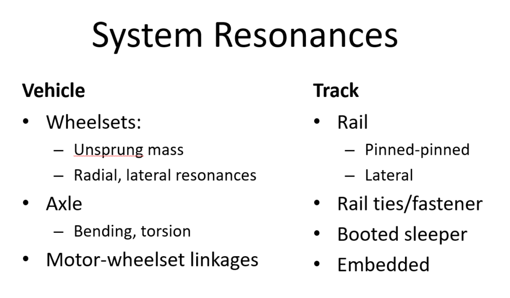
These systems have all taken steps over time to remediate and manage corrugation, but corrugation is persistent. “Even if corrugation is addressed via design and maintenance, we should expect it to reappear,” Magel said. The reason for this is the fundamental mechanisms involved; the vehicle and track system itself is a combination of many mechanical components, each with its own mass, stiffness, and dampening, and their resultant resonances. On top of that, the wheel/rail interface sees a wide range of operating conditions, including:
- new and worn profiles
- lubricated and non-lubricated rail
- dry and wet seasons
- up-grade and down-grade running
- braking and accelerating
- and many others
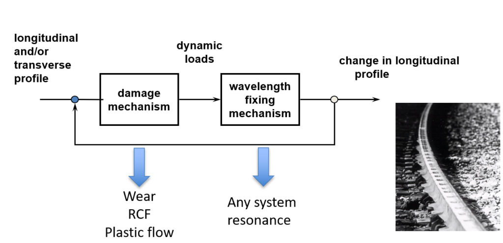
The wheel/rail system is always experiencing at least one of three damage mechanisms: rolling contact fatigue (RCF), plastic flow, and wear.
“When all these systems and their resonances are brought together, there is an inevitable feedback loop that’s created,” Magel said, in which the rate at which damage occurs increases and reinforces the wavelength fixing mechanism. There is always a damage mechanism (often multiple) and always a dominant resonance, and while neither of these can be eliminated, they can be treated. “That’s the reason it’s important to preventively grind; grinding arrests that feedback loop at an early state.” he said.
An investigation into severe corrugation and gauge-corner collapse on a transit system in South America highlights the complex interaction of all these systems. In this case, the rail showed no evidence of RCF or plastic flow, indicating that the damage mechanism was strictly wear, Magel said. In order to pinpoint the cause of the corrugation, the investigators took measurements to identify the corrugation wavelength-fixing mechanism in the system. In this case, it turned out to be a torsional bending of the sleeper that caused the rail to vibrate vertically as the trains passed. “The culprit being sleeper resonance was completely unexpected,” Magel said. Since replacing all of the sleepers would have been a prohibitively expensive fix, the transit system instead set its focus on the wear mechanism. This took the form an extensive grinding program to remove the corrugation, and the introduction of multiple rail profiles to improve the wear pattern of the wheels and steering in curves.
“Rail corrugation is a natural phenomenon that will always assert itself, so as a matter of course, there should be a maintenance plan in place to address it,” Magel aid. The challenge then is developing more efficient and cost-effective methods of corrugation remediation, a process that begins with good data.
Working With Data
Corrugation measurements, such as those taken by the Corrugation Analysis Trolley (CAT), which essentially provides a rail-roughness measurement, are an industry standard metric. But the raw data that comes from the CAT must be cleaned and processed in order to become clear and actionable information. The University of Manitoba has recently been involved a project to summarize this raw data – a project that aims to enhance the practical applicability of CAT data.
“The spatial summarization of RMS (root mean square) CAT data presents challenges in that the corrugation, the measurement of the corrugation, and the methods for removing corrugation (rail grinding) all happen at different scales,” said Jonathan Regehr, Associate Professor at the University of Manitoba. The goal then is to find a way to mesh these different dimensional scales.
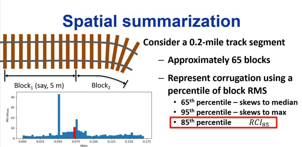
Consider, for example, a 0.2-mile segment of rail. Given the granularity of corrugation measurement, what is the optimal way to describe the RMS – effectively the measure of the roughness of an oscillating signal — of corrugation across the entire segment? The team at the University of Manitoba ultimately settled on the 85th percentile of the RMS value – a suitable compromise between the median and maximum – for their Rail Corrugation Index (RCI85).
This brought up further questions regarding the breakdown of track segments. “The 0.2-mile block is somewhat arbitrary and perhaps not the most optimal RMS block in a practical setting,” Regehr said. Track segments are typically defined by their geometry features, such as tangents, spirals, and curves. It’s also important to differentiate between the high and low rails. These considerations also affect the actual collection of raw data using the CAT, as the probe positions are variable and are typically positioned on or near the running band of a given rail. There are also going to be significant differences between ballasted, direct fixation, and embedded rail — differences that are critical to corrugation analysis,” he said.
Finally, Regehr noted the importance of measuring corrugation at the right time. While there may be value in measuring at regular intervals based on time or MGT, the most useful measurements are often those taken just before and immediately after rail grinding. “Often we lack the before-and-after picture to evaluate the immediate effectiveness of the [rail grinding] intervention,” he said.
Effects of Automatic Train Operation
Automatic Train Operation (ATO) was first introduced as a purpose-built line-scale system in 1968 on London Underground’s Victoria Line. ATO operations have evolved and spread since then and continue to do so as new systems come online. Today, the majority of London’s lines operate with ATO. The precision and efficiency of ATO has led to tighter timetables, and more frequent service.
But, as is the case on Vancouver’s Skytrain, ATO can introduce or exacerbate problems of its own. There are a number of damage modes specifically associated with ATO. These are issues Andy Vickerstaff, , Senior Wheel-Rail Interface Engineer– Transport for London, is intimately familiar with in his experience at London Underground.
Part of the reason ATO was introduced and expanded upon was to increase overall system capacity. In terms of service, the top or target speed doesn’t have as much of an impact as how quickly trains can accelerate and brake — particularly in short station-to-station sections. “This is something that ATO handles particularly effectively,” Vickerstaff said. The resultant increase in service, however, also means an increase in tonnage that the system experiences. “We’re running in excess of 40 MGT in some of these deep tube sections now.”.
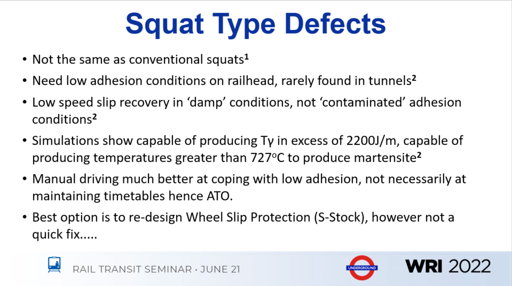
While London Underground is typically thought of primarily as a subway system, 50% of the system is ballasted open track. This was where the most concerning studs (squat type defects) first started to appear, Vickerstaff said. Over time, LU’s wheel/rail interface and track specialists noticed a number of trends regarding the formation and appearance of studs:
- They are almost always in open track sections.
- They are always on lines with AC traction.
- They are concentrated in areas of high-congestion, but rarely in platforms themselves.
- A martensistic layer is present above the cracks.
- They first began to appear in large numbers after the introduction of ATO.
- They require low-adhesion conditions on the railhead to initiate.
Taken altogether, the primary culprit appears to be related to ATO. After a number of studies and investigations, LU determined that the best, most efficient method to address stud formation was to redesign the Wheel Slip Protection traction package, a subsystem of the ATO software. “But,” Vickerstaff said, “while this might seem like a quick fix, it is not. It has been in development for a decade.” As a result, it has been and will continue to be necessary to monitor and remediate corrugation and studs as necessary.
One approach that LU, like other systems, has taken is to implement a preventive grinding program. “It’s important to note that you can’t actually remove the studs — they’re simply too deep and it’s too much material to remove. But we can target the martensitic layer,” he said. This approach has proven to be effective at lowering the rate of severe stud development and propagation, but it also requires a significant grinding effort in terms of time and money, he added.
Corrugation is also a major issue on the London Underground. Over the past several years, the LU has put significant effort into better understanding the root causes of corrugation on its lines. These efforts have led to a classification system whereby corrugation can be attributed to one of the following modes:
- P2 resonance: a function of the unsprung mass of the wheelset and track stiffness.
- Pinned-pinned: a function of sleeper spacing.
- Rutting: a function of lateral wheelset oscillation (typically found in very tight curves).
- Trackform specific: believed to be a function of resonance through the rail pad and clip (this type of corrugation grows very quickly).
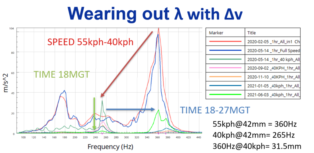
The lack of traffic during the Covid pandemic provided the London Underground with a unique opportunity to perform experiments on the relationship between train speed and corrugation formation at a number of different sites.
One site, in particular, showed significant corrugation occurring at a frequency of 360 Hz. “We found that moving from 55kph to 40kph shifted the frequency to 265hz,” Vickerstaff said. That speed restriction was left in place for nine months, during which time, the 360 Hz frequency corrugation was effectively worn out and replaced by a less severe corrugation pattern in a different frequency band. “This demonstrates the significance of a constant frequency,” he said, which is intrinsic to the consistent operating behavior of ATO systems.
Another series of studies conduction by LU noted that rail roughness and corrugation growth, post-grinding, tends to occur at a much slower rate in sections with more train speed variability than those with more consistent speeds. This ties back to the core concept of a wavelength-fixing mechanism and system resonances; anything that disrupts the feedback loop works counter to it, thus slowing the development of corrugation in the dominant frequency.
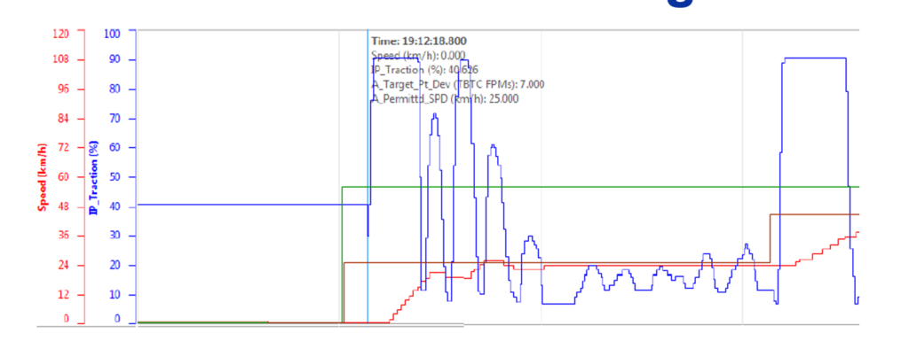
A final point of significance regarding ATO is that unlike a human driver, the system rare coasts. “Particularly at lower speeds, ATO maintains a steady speed by constantly accelerating and braking.” he said, “and the simple fact is: traction destroys curving.” The more traction that is applied through a curve, the more likely that corrugation and RCF are to develop.
As ATO systems continue to be refined, insights like those gleaned at London Underground can help find a better balance between timetable efficiency and wheel/rail health; and future ATO systems may actively help mitigate corrugation rather than contribute to it.
Noise and Vibration
Excess noise and vibration draw complaints. They are also indicative of asset condition; symptoms of something gone wrong at the wheel/rail or vehicle/track interface. The primary sources of noise in transit systems are: rolling (corrugation), rumble, flat spots, ground-borne vibrations, squeal, and flanging, said Davey Mitchell, Commercial Manager of Friction Management at L.B. Foster.
Sharp curves, in particular, are typically problematic areas with a number of overlapping noise sources. Corrugation is often found in sharp curves, and these curves are often where wheel squeal and flanging noise are most pronounced. Wheel squeal is produced by stick-slip oscillations which cause the wheels to vibrate and project like a loudspeaker. “[Wheel squeal] is something that’s going to generate a lot of complaints from both riders and the people who live near the system,” Mitchell said, “so it’s a high-priority issue.” Positive-friction introduced though friction modifiers is generally the most effective way to lessen wheel squeal, he added.
Flanging, which, like wheel squeal, is a source of high pitch noise, is generated by a wheelset attempting to navigate a curve with insufficient rolling radius difference, resulting in a large angle of attack, and, thus, heavy flange contact. This typically occurs on the high rail, but it can affect the low rail and restraining rail. Gage-face lubrication as well as top-of-rail (TOR) friction modifiers can be used together to lessen this source of noise.
In 2018, Skytrain commissioned a broad study in response to various noise concerns. The study measured corrugation development and growth over three years in both curve and tangent track. At the time, Skytrain was grinding the track included in the study every three months as a matter of course for corrugation mitigation. So, one aspect of the investigation measured the effect of TOR FM on the rate of noise- and corrugation-increase, post-grinding. They found that, versus dry rail, the application of TOR FM reduced noise over a 3-month period by 8 to 9dB, and over a six-month period by 5 to 7dB. “This was a success not only in terms of reduced noise, but it also presented the opportunity to save money on grinding by reducing the frequency required,” he said.
The benefits that TOR FM can provide are well known, as are the benefits of gauge-face lubrication. But some cases require the combination of the two to achieve optimal results. L.B. Foster worked on one such heavy rail subway system in 2021. This system used horizontal restraining rail in most of its curves, so the aim of the project was to determine the sources of the noise, better understand restraining rail-borne noise, and identify the most effective mitigation strategy.
L.B. Foster instrumented the worst-case curve to collect noise and vibration data on both running rails and the restraining rail. The team then tested a number of GF lubrication and TOR FM products and different combinations thereof. After a number of trials, the data showed the most substantial decrease in noise was achieved through a combination of gauge face lubrication on the running rail and the restraining rail, and TOR FM on the running rails. The data also showed that in this case, the restraining rail contact did not appear to be a significant source of noise, however the high rate of wear of the restraining rail was of concern to the customer. As a result, lubrication of the restraining rail was recommended as part of the overall friction management program. “TOR FM by itself was quite effective at reducing noise, but the best results were achieved through a combination products,” Mitchell said.
Of course, multiple applicators and multiple friction management products add up quickly, and systems are always looking for the most efficient and cost-effective strategies to mitigate their concerns. “A common question, if a system doesn’t have the resources for both TOR FM and GF lubrication, which is the better investment?” Mitchell said. Unfortunately, there is no one-size fits all approach. The answer can differ depending on the specific site, and the conditions may fluctuate such that neither strategy alone is always the better choice, he said. This is particularly true in challenging areas with multiple potential sources of noise.
Data collection and analysis on this project is still underway, with future areas of investigation to focus on RMS and peak acceleration values of rail vibration, frequency of rail vibration, and whether these analyses may help to address noise concerns with greater precision.
In another pair of recent studies, Emova, the Buenos Aires Metro, looked to friction management to mitigate unexpectedly high wheel and rail wear in one case, and complaints of excessive ground-borne vibrations and corrugation in another. These studies concerned the E and H lines, respectively.
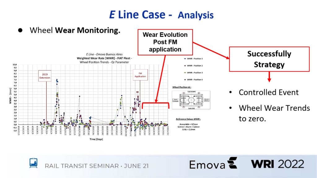
In the case of the E Line, the problems arose shortly after a 2-km extension went into service. “We saw sudden and unexpected flange wear almost as soon as the extension went into service,” said Emova ‘s Guido Ambrosio. The first step of the study was to comprehensively measure every wheel, taking into account the wheel’s location on the car and within the consist. “In our case, the consists are fixed, so a wheel in a given position will tend to perform in a consistent manner,” he said. This data was then compared to the track geometry and car-mounted accelerometer measurements. This, in turn, led the investigation to focus in on two specific curves in the new extension as the culprits. The combined data sets indicated that bogies moving through these curves were experiencing high angles of attack, resulting in heavy gauge and flange wear.
“Previous experience with similar issues in the past had already shown us the effectiveness of TOR friction modifier in reducing the [lateral] stresses and angle of attack,” Ambrosio said. So Emova installed a TOR FM applicator just before the first problematic curve. Tests taken in the field post-TOR installation showed that the FM material carried far enough to benefit both curves. Wheel wear measurements taken post FM application confirmed the success of the mitigation strategy. “Our flange and gage wear dropped significantly, and lateral forces were drastically reduced — it was quite a success,” he said.
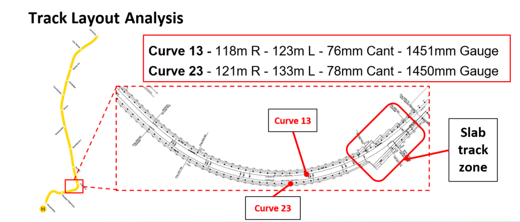
The H Line case study began as a result of numerous complaints about ground-borne vibrations from people living along the H Line. The data-collection phase of the investigation consisted of wheelset parameter measurements, vibration measurement and analyses on both infrastructure and rolling stock, and transverse acceleration mapping, said Emova’s Gabriel Ehler.
Track inspection indicated that the most severe corrugation on the line appeared on the low rails of the inbound and outbound tracks on a specific curve that featured a transition zone from concrete slab to ballasted track near the end/beginning of the curve, depending on direction of travel. In the course of the study, the team collected data from a number of sources:
- Infrastructure vibration measurements at the transitions into and out of the slab track zone, as well as within the ballasted curve body.
- Bogie behavior from axle-mounted accelerometers.
- Noise dB and frequency data.
- Wheel measurement data.
The wheel measurement data showed a large number of out-of-round and corrugated wheels. Both of these wear patterns were asymmetric, occurring primarily on the wheels that encountered the low rail of the target curve, Ehler said. ” “Both the wheel condition and the intense vibrations were unique to this line, which indicated an especially volatile wheel/rail interface condition.”
Analysis of the data led to a multi-pronged solution that included TOR FM application, rail grinding to remove the existing corrugation, and wheel reprofiling.
Post-grind testing indicated that ground-born vibrations fell sharply. Vibration data taken on the post-grind rail with the addition of a TOR friction modifier resulted in a further reduction in vibration and noise. As a result, TOR FM applicators were installed at the start of the curve (relative to direction of travel) on both tracks. Finally, the H Line fleet wheels were reprofiled to remove corrugation and out-of-roundness. Since this multi-faceted mitigation strategy was put into place, the problems that led to the vibration complaints have not reappeared, Ehler said.
These cases hammer home the importance of taking an integrated, system-based approach to addressing problems that arise from wheel/rail interaction. Across a wide variety of transit systems experiencing a variety of adverse interface conditions, the same few techniques and mitigation strategies combine and recombine to solve problems. As data collection and analysis becomes more sophisticated, transit systems can better target and more efficiently deploy their resources to make practical, lasting improvements to their most valuable assets.

Jeff Tuzik is Managing Editor of Interface Journal

