WRI 2014 Transit: A Systems Approach to Wheel/Rail Interaction
by Jeff Tuzik
The 20th annual Wheel/Rail Interaction Conference drew a record number of attendees and speakers from around the world. They came to contribute to and draw from the growing body of knowledge on wheel/rail interaction. Since the conference began 20 years ago, the industry has come a long way and learned some hard lessons. Speakers at the Rail Transit conference looked back at some of those lessons, and forward to new studies and technologies.
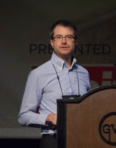
“I’ve seen railways fall apart completely as a result of not understanding how to manage [the wheel/rail] interface.” — Paul Baker. Photo by Jack Lindquist.
“I’ve seen railways fall apart completely as a result of not understanding how to manage this interface,” Baker said.
Wheel/rail interaction is a complex process that is influenced by many variables. Among the most significant are:
• Rail profile and metallurgy
• Wheel profile and metallurgy
• Track support and structures
• Primary vehicle suspension systems
• Environmental factors / weather
• Friction management
• Traction and power
Because these variables cut across all departments of rail transit operations, collaboration between departments is critical to properly managing wheel/rail interaction from the design, to operation, to maintenance phases. Baker noted the historic tendency for departments to operate independently of each other and view each part of the wheel/rail system as isolated components. Experience has shown that this type of “silo mentality” can quickly bring an operation to its knees.
That said, it’s not always easy to make the business case for investing significant amounts of time and money into wheel/rail interaction. “Short-term goals must be balanced with the long-term reliability and safety concerns,” Baker said. But close attention to wheel/rail interaction can help prevent a catastrophic failure. It can also help to address costly “political” issues like wheel/rail-generated noise.
Noise concerns are at the root of a growing trend in public objection to new rail projects in Australia. Residents who have lived near rail lines for years without issue are growing increasingly concerned and outspoken about rising operational noise. Unfortunately, commonly-used noise mitigation barriers are costly and are frequent targets of public objection.
Besides, noise barriers don’t address the source of the noise, said Dave Anderson, Director of Acoustics Studio Pty Ltd. You have to take a systems approach to effectively control noise. Anderson presented two recent case studies by the Cooperative Research Centers (CRC) in Australia which examined the systemic sources of rolling and curve noise.
In Australian studies, rolling noise is typically measured using the Track Wheel Interface Noise Software or TWINS. This software analyzes various parameters such as the surface finish of the wheels and rails and their interaction with rolling stock components to generate an estimate of total generated noise. For current and future studies, the CRC revamped and enhanced TWINS to create the Railway Rolling Noise Prediction Software.
Rolling noise is greatly affected by wheel and rail surface roughness. As a result, rail grinding can be an effective way to cut noise levels. Over the past 10 years, Network Rail in the UK has been able to reduce network-wide noise levels by 9dBA thanks to its progressive grinding program. Similarly, the Epping Chatsworth line in Sydney, Australia saw up to a 9dBA noise reduction in some sections, with an average reduction of 4dBA. Installation of rail dampers resulted in a further 4dBA reduction.
Curve noise is typically characterized by squeal and flanging noise. Conventional wisdom has been that squeal occurs as a top-of-rail phenomenon on the low rail and that flanging noise occurs as a result of flange contact on the high rail. The CRC determined that squeal can also be generated by flange contact at the gauge corner of the high rail. By changing the wheel/rail contact from conformal to two-point contact through rail grinding, this type of squeal can be mitigated.
Noise concerns can look like a minor issue in comparison to other issues stemming from a mismanaged wheel/rail interface.
The early struggles of the LA Metro provided an example of the failure to take a systems approach to wheel/rail interaction — as well as the steps that are required to set things straight. Designed as a state-of-the-art heavy rail transit line, the LA Metro Subway quickly ran into trouble. Wheels and switch points throughout the system required replacement after fewer than 20,000 miles of revenue service. “It was a fiasco,” said Wyman Jones, Director of Rail Operations Engineering at LA Metro.
The source of the dramatic wear was the vehicles’ poor curving characteristics. The newly-acquired vehicles were designed for high-speed stability using trucks designed with a 34 1/4 in. wheel diameter. The track structure and alignment was designed for typical transit wheels measuring between 26 and 28 in. diameter. In addition to excessive wheel and rail wear, the mismatch caused excessive noise at crossovers and in curves, truck nosing and rotational stiffness, and most significantly, wheel flange climb.
A minor wheel-climb derailment brought additional scrutiny to bear on the problem; cameras were installed to capture the wheel flanging in action. “We watched on camera — the wheel was flange-climbing at 12 mph,” Jones said. Steps were quickly taken to remediate the problem: speeds were reduced to 10 mph in crossovers; wheel profiles were changed from the AAR 1:20 to the AAR 1-B — a change that resulted in a minor extension of wheel life: from 20,000 miles to roughly 30,000 miles.
Advanced Rail Management was brought in as a consultant, and recommended several changes:
• Installation of flange lubricators
• Development of a custom wheel profile
• Development of a custom rail profile and grinding regime
• Modification of primary suspension to improve steering
• Changing of side bearing plates to reduce friction
Some of the changes were easier (and took less time) to implement than others, but by following the recommendations, wheel life rose dramatically — from 30,000 miles to 200,000 miles. With further optimization – the adoption of the AREMA standard spiral turnout, and modified crossover design – this figure climbed to nearly 550,000 miles, Jones said.
The LA Metro experience shows the importance of taking a systems approach to wheel/rail interaction at the design phase; and it illustrates the benefits of investing the time and money to optimize a system that’s already in place. And, of course, you can’t optimize wheel/rail interaction if you can’t measure it.
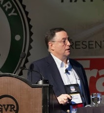
Antonio Cabrera of the NYCT discussed the benefits automated track inspection systems have over traditional inspection crews. Photo by Jack Lindquist.
New York City Transit (NYCT) measures and monitors track conditions on its system with a pair of Automated Track Geometry Cars (TCG3 and TCG4). Autonomous track inspection technologies are important to rail transit systems for a number of reasons, said Antonio Cabrera, Track Engineering Officer at NYCT. The first is safety; autonomous inspection minimizes the inherent dangers faced by traditional walking inspectors by keeping crews off the right-of-way. Second, autonomous inspection technologies can increase the operational frequency of inspection and cover significantly greater distances while decreasing the adverse operational impacts to the system that walking inspection teams create. Third is accuracy; these technologies can take more precise and more frequent measurements than traditional hand tools.
“You’re ensuring the safety of the inspectors and you’re getting a recorded, objective inspection,” Cabrera said of the TGC program.
The NYCT’s first autonomous inspection car (TGC1) went into service in 1984. Compared to today’s technology, its capabilities were limited. The current models (TGC3 and TGC4, which went into operation in 2007 and 2008, respectively) can operate at speeds of up to 75 mph and measure:
• Track geometry under dynamic loading
• Rail wear
• Rail flaws via ultrasonic detection
• Third Rail gauge and height
• Flangeways
• Tunnel clearance
• Power cable/electricity hotspots via thermal imaging
These vehicles also take video of the rail, tie plates and fasteners. Inspection personnel can use this information to find flaws that the system can’t detect autonomously.
In 2012, NYCT, working with a grant from the FTA Office of Research, began a project with the following objectives:
• Improve the safety of transit workers by limiting inspectors’ exposure to the right-of-way.
• Enhance the quality of inspection by increasing the frequency of inspection and defect reporting.
• Establish an optimum frequency of track and infrastructure inspection to maintain a state of good repair of track and infrastructure.
• Provide track supervisors, managers, and MTA-NYCT’s executives with detailed inspection tools for the identification, prioritization, planning, and execution of maintenance, repairs, and reconstruction of track systems.
• Maximize the TGC’s functionality by performing full track system inspections including the power/third rail and field side of the running rails.
Phase 1 of the project explored the engineering feasibility of installing additional video systems focused on the third rail and the field side of the rails. This phase confirmed that camera systems could produce sharp video of the target locations. Phase 2 was to manufacture and install the necessary hardware. Phase 3 focused on customizing the video review software to include a series of ease-of-use and functionality upgrades. Phase 4 was the test run of the modified TGC4 on track C1 and C2 of the Flushing Line between Times Square and Queensboro Plaza.
During the test, the TGC4 detected 90 defects/conditions on C1 and 96 on C2. By comparison, track walker inspections (consisting of a four-person team, moving at a rate of 15,000 ft per six-hour shift) detected 36 defects/conditions on C1 and 41 on C2. The TGC4 completed its inspection in less than 15 minutes per track, without exposing personnel to safety hazards or tacking the track out of service, Cabrera said.
For the exception or defect data to be useful, maintenance crews or follow-up inspections have to be able locate and confirm defects found by automated inspection vehicles. To that end, Holland L.P. and the Chicago Transit Authority (CTA) installed Radio-Frequency Identification (RFID) tags in track to provide precise reference data that can be used to pinpoint the location of geometry exceptions or track events.
Holland fastened RFID tags to the base of the rail at 500 ft intervals and linked these tags to location data including: line color, branch, track number, and chain marker. All flagged exceptions included their distance to the nearest RFID tag or other track event (such as a frog, platform or switch). The exception report was then uploaded into a handheld unit used by maintenance personnel to confirm the exception or flaw location based on the RFID tag in-track.
The incorporation of RFID data into the track geometry testing program delivered a higher level of accuracy and ease-of-use than the existing milepost-based location tagging, said Andie Berry, Product Development Manager for the Railway Measurement Systems and Services Division at Holland. It proved that RFID tagging has the potential to improve the efficiency of existing maintenance programs without major overhaul or prohibitive upgrade costs.

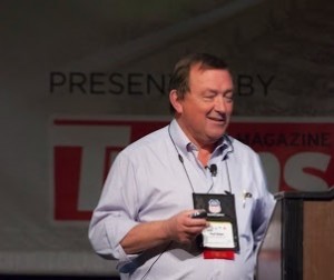
“RFID can essentially replace or augment the forward observation techniques that go into your data collection,” — Andie Berry. Photo by Jack Lindquist
“RFID can essentially replace or augment the forward observation techniques that go into your data collection,” Berry said.
Beyond track geometry, another important component of wheel/rail interaction is friction management. A case study on the implementation of solid stick lubricant on the Delhi Metro showed that the technology can have a strong positive effect on wheel life.
Solid stick lubricant (SSL) is applied directly to the wheel flange to reduce the coefficient of friction as low as possible in order to minimize wheel-flange and gauge-face wear. “Trials typically measure the friction reduction levels to between 20% and 50%,” Said Ron Hui, Global Manager of Engineering, Solid Stick Technology, for LB Foster Rail Technologies.
Solid stick friction management (SSFM), which is less common, is applied to the wheel tread in order to bring the coefficient of friction down the ideal range of 0.3 to 0.4 to reduce tread wear and manage corrugation.
Solid stick products are mounted via brackets on the vehicle’s truck and applied to the wheel by a constant force spring. Despite the constant rate of application, stick lubricant life varies based on the characteristics of the rail system. High-speed, low-curvature lines can achieve a stick life of up to 180 km per gram of material, while high-curvature metro lines may get down to 40 km per gram of material, Hui said. The number of SSL applicator units (coverage rate) that a particular system requires can be determined by the flange wear index, which combines existing track wear and curvature data, and Vampire® simulation data.
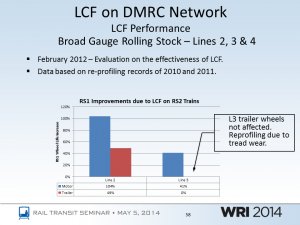
The Delhi Metro Rail Corporation (DMRC) began implementation of SSL systems in 2010 with the goals of increasing wheel flange life, reducing gauge-face wear, and reducing wheel flanging noise. Hui noted that the study was complicated by the fact that the DMRC operates rolling stock from two manufacturers: Rotem/BEML and Bombardier Transportation (BT). For the time frame of the case study, Rotem/BEML trains on lines 2, 3 and 4 were not yet equipped with SSL hardware.
BT trains on Line 2 were outfitted with 25% SSL coverage – meaning that 25% of the wheels per train were equipped with SSL applicators. Rotem/BEML cars running on the same line without any SSL coverage, however, brought the system effective coverage to 21.6%. BT trains on Lines 3 and 4 were also outfitted with 25% coverage. A higher number of Rotem/BEML trains without SSL, however, brought the system effective coverage to 12.3%.
The DMRC compared pre- and post-SSL re-profiling data in order to quantify the effectiveness of the lubrication program. The results showed that Line 2 achieved a 104% increase in powered-wheel life, and a 49% increase in trailing-wheel life, Hui said. Lines 3 and 4 achieved a 41% increase in powered-wheel life and no measured increase in trailing-wheel life (these wheels were re-profiled due to tread wear).
Future work on the DMRC is focused on implementation of SSL on all trains to achieve a uniform level of coverage, as well as expanding coverage on lines with a high flange-wear index score.
Milling: Benefits and Limitations
While rail grinding has long been used to manage wheel/rail interaction, rail milling has begun generating a buzz in North America. Milling is common practice in parts of Europe and continues to gain market share as a method for correcting a variety of rail head defects. Bakerail’s Paul Baker pointed out the benefits and the limitations of rail milling as gleaned from projects on a number of light rail and heavy metro lines.
The milling machines in these projects were tasked with addressing a broad range of rail defects, including rolling contact fatigue, crushed rail, squat-type defects, and rail profile degradation. Milling proved capable of correcting these problems, but not without first overcoming challenges that were unique to each operating environment. For example:
• Lubrication systems and wayside monitoring devices must be removed prior to milling.
• Rail must be properly fastened and aligned to prevent “chattering” against the milling head.
• Excessive plastic flow may extend the rail head width beyond that of the milling head, requiring multiple passes in order to restore the profile.
• Special track such as grooved rail requires a custom milling head design.
Despite these considerations, milling has proven to be an adaptable and effective addition to the toolkit for managing a broad range of rail conditions and defects, Baker said. And new developments such as rotational planning, which allows a milling machine to adjust its target profile without having to stop and change out the milling heads, are on the horizon.
Transit Project Delivery Contracts
While not a “hands on” wheel/rail interaction issue, the conference also addressed rail transit contracts and their impact on near- and long-term maintenance issues. “Does the contract type affect long-term maintenance?” asked Chris Burner, Chief Project Officer at the Metro Gold Line Foothill Extension Construction Authority. Unfortunately there is no simple answer; each type of contract type has the potential to succeed.
“Design-bid-build (DBB) works very well when you have a strong owner who wants to lead the process,” said Kevin Vokey, Director of Rail Services at SNC-Lavalin, Inc. The drawback to this type of contract is that it can be complicated by the silo-mentality between the engineer and contractor.
The design-build (DB) model has the benefit of bringing the engineer and contractor together for greater synergy between design and construction. This removes the siloing and encourages the engineering team to take a more active role in the construction phase, or should the need for a re-design arise.
Ron Benson, Deputy General Manager of Rail Systems Infrastructure at the Utah Transit Authority, noted that the UTA Rail System has issued only DB and DBB contracts in the past. “We knew we were going to have to maintain everything. We couldn’t hand it off to anybody,” he said. Because the UTA Rail system also runs freight on its track, the design specifications fall under FRA jurisdiction; “It made a lot of our design and build standards simpler,” Benson said.
The P3 or design-build-operate-maintain (DBOM) model brings the typically separate functions of design, construction and maintenance together. The DBOM team is responsible for the entire lifecycle cost of the project and is therefore particularly cognizant of the long-term effects of design and construction choices. “From a transit authority perspective, the benefit of the P3 model is that if something goes wrong, the DBOM team has to set it right,” Vokey said.
Mike McGinley, Senior Consultant at Advanced Rail Management, noted the similarities between DBOM contracts and private railroad industry projects. “Silo thinking – protecting your own cost exposure to things regardless of consequences elsewhere — is a battle still fought in the railroad industry and even within a DBOM partnership. There’s a natural tension, but it can be a creative tension.” He said.
A systems assurance/performance demonstration test is one way to alleviate concerns about maintenance and lifecycle costs when operating outside a DBOM model. “We require the contractor to address certain maintainability issues and achieve certain reliability goals before the system goes into revenue service,” Burner said.
McGinley summed it all up with a simple, but important message: “The wheel/rail interface is a microscopic sample of these kinds of competing cost pressures – short term and long term,” he said. “We need to take a holistic approach to these infrastructure problems.”
![]()
Jeff Tuzik is Managing Editor of Interface Journal.

