Mitigating Rolling Contact Fatigue: An Overview for 2023
by Jeff Tuzik

Rolling contact fatigue (RCF) affects railroads and transit systems globally. The effects of RCF damage range from poor ride quality and excessive noise, to shelling and spalling so deep and widespread that rail sections must be replaced. Over time, the railroad and transit industries have developed tools to detect and measure RCF and a suite of techniques to mitigate it.
Whether on wheel or rail, RCF appears similarly. Light cracking, progressing to intermediate cracking, to heavy cracking and incipient shelling, and finally significant shelling. Another manifestation of RCF is gauge corner collapse and deep-seated shells. These occur when there is significant loading on the gauge corner, especially on the high rail, leading to a collapse of the corner and large pieces of rail breaking (or shelling) out. In some cases of gauge corner collapse (sometimes before the rail material has sloughed off), the shell can meet an internal flaw and lead to a transverse defect and a broken rail, Eric Magel, Principal Consultant with EM-WRI Consulting Inc. and project consultant with Advanced Rail Management/Global Rail Group, told participants at the 2023 Wheel/Rail Interaction Heavy Haul Conference.
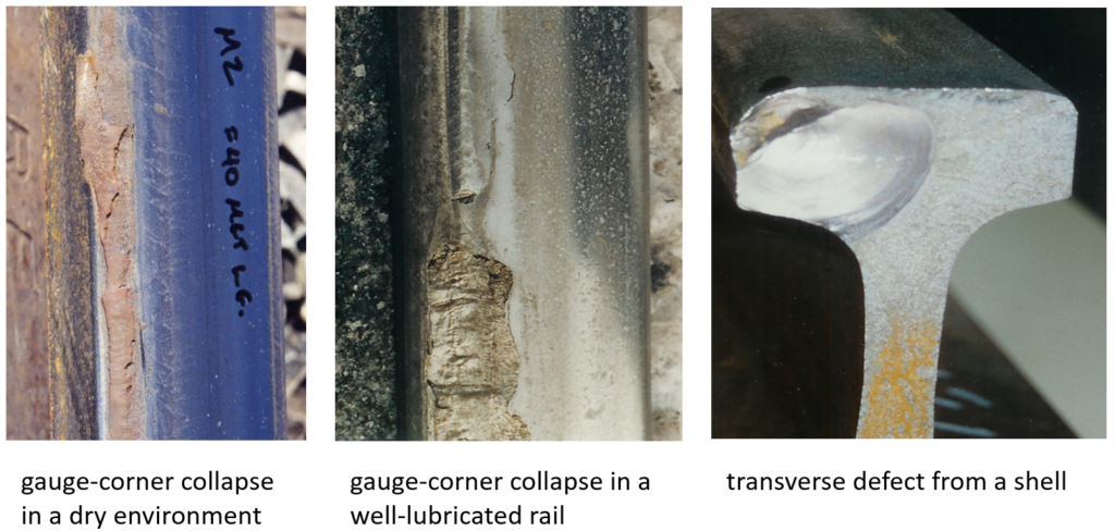
RCF can also manifest as squats or studs (squat type defects). These have become more common in North America in the past 20 years, but they represent a fairly universal problem. As studs progress, they can shell or break out of the rail, leaving defects that are typically 2mm to 4mm deep, Magel said. Crushed heads, a defect similar in appearance to squats and studs, have historically been a problem on some freight railroads. These start as cracks that develop toward the gauge, typically in older, softer steels, propagate towards the crown of the rail, lead to a depression in the rail head which is then battered by nearly every passing wheel, in some cases causing the head of the rail to collapse.
RCF, especially in its early stages, can be difficult to detect. Historically, and still today, much of this detection is done visually on freight railroads by track inspectors from a hi-rail vehicle moving at speeds below 25 mph. Depending on the severity, the inspector can also feel and hear RCF while traveling over it.
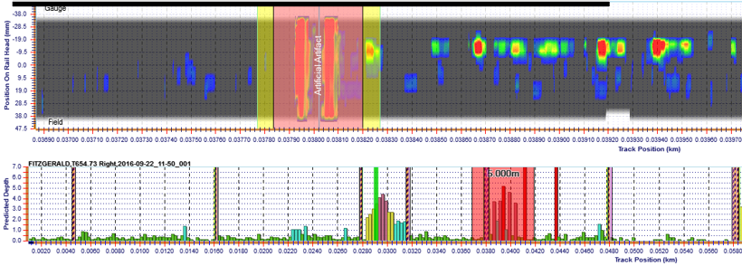
Within the past 15 years, electromagnetic measurement devices have begun to emerge; before then, there was no objective way to measure or quantify RCF. A number of walking-stick systems are now available to the North American rail industry including: the Rohmann Draisine and Goldschmidt Trackscan Mira which use eddy current, the MRX rail surface condition monitoring system that uses magnetic flux and the Athena RAGA which uses electromagnetic field imaging. Some of these have been adapted to be towed behind a hi-rail vehicle, enabling larger scale data collection on a regular basis, Magel said.
These devices typically display data as a strip chart indicating the number of cracks and maximum crack depth in a given location. The MRX system can also produce a contour chart which indicates both the severity and position of the RCF damage. Machine vision is a relatively new entrant in RCF detection; these include the ENSCO Rail Surface Inspection System, the Loram Rail Inspection Vehicle, and Plasser & Theurer’s machine vision system. “These [machine vision] systems are pretty good at detecting cracks and RCF, but the trick is to quantify that somehow, based on severity,” he said.
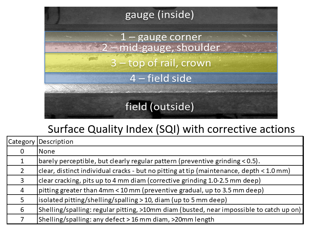
“How can we take that data and put it in a useful form?” Magel asked. He cited Dan Hampton, the Director of Contract Services at CSX Transportation, who has championed the development of a common scoring approach to RCF — a shared surface quality index. The idea is to divide the rail into distinct bands and apply a common severity scale that can be informed by and compared to data coming from any type of RCF measurement device. An SQI like this would make it easier to turn data into actionable information, Magel said.
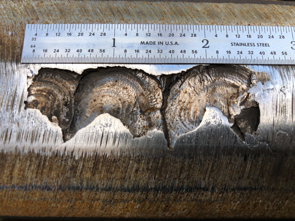
Magel identified three primary root causes of RCF. The first is overstressing the steel. The combination of excessive contact stress and shearing traction at the wheel/rail contact patch causes plastic flow; the material work-hardens and continues to strain until it exhausts its ductility and cracks. The crack forms along the line of the deformed layers in the rail. Depending on the conditions, these cracks may wear away. If they don’t wear fast enough, they can propagate up to the point of shelling (see figure 4).
The second root cause is overstressing of the gauge corner, which can lead to gauge-corner collapse. Many conditions can lead to excessive loading on the gauge corner. These include profile shape, plastic flow, and outward rotation of the rail (also called dynamic gauge widening). “Even under perfect lubrication, you can collapse the gauge corner,” Magel said.
The third mechanism relates to martensite, a thermally-transformed layer that forms under very high creepages and contact stresses between the wheel and rail. Martensite can form on the rail due to wheel-slip events, for example, but it can take other forms, too. On transit systems, martensite can appear as a thin layer scattered throughout the system; this occurs due to generally high and repetitive creepage force at the contact patch due to propulsion systems and operations seeking higher tractive efforts. This layer may wear away without incident, but it can also initiate cracks that propagate via classical RCF mechanics, Magel said. Defects initiated in this way can manifest as squat-type defects (studs), and by the time they are visible, the depth of damage can be 3mm deep and many centimeters long.
With the root causes of RCF in mind, the following conditions are known to promote RCF development:
- Mismatched wheel/rail transverse profiles
- High dynamic loads
- Track irregularities (increased dynamic loading and creepage)
- Low material strength (softer steels are more prone to RCF)
- Misaligned wheelsets (high angle of attack and creepage)
- Excessive friction
- Excessive creepage
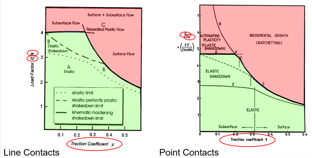
Magel pointed out that the likelihood of RCF to develop at a given location can be illustrated by a shakedown diagram (see figure 5). The Y-axis is the ratio of the contact stress (Pₒ) at a particular wheel/rail contact point to the strength of the material in shear (the value in K). The X-axis is the traction coefficient, which is the ratio of the shearing forces divided by the normal forces at the wheel/rail contact. Any contact condition that falls in the red-highlighted area will contribute to RCF development. Moving from the red area to the green area requires either increasing material strength, lowering contact stress, or reducing traction coefficient (or some combination of the three), he said. From a practical standpoint, there are many ways to approach this.
Improved wheel profiles can help manage RCF. In the early 1990s, the Quebec Cartier Mining railway (QCM) struggled with wheels that failed due to shelling very early in their service life — in the 10-to-20-thousand-mile range. A study indicated that their wheel profile was a poor match for their rail profile, resulting in excessive creepage and contact stress. Magel, working with Joe Kalousek, at the National Research Council of Canada NRCC), developed a customized wheel profile, which upon implementation, increased wheel life by 60%.
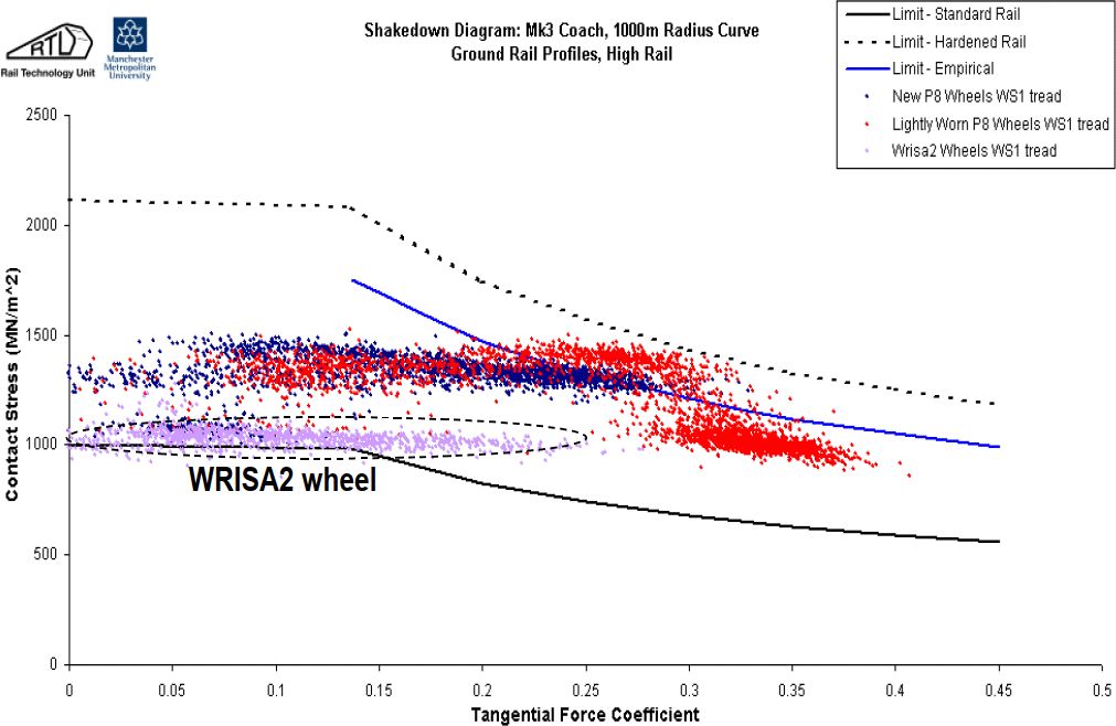
On the basis of that success, Magel and Kalousek and the NRC developed a wheel profile (the NRC-ASW) for the Canadian National and Canadian Pacific railroads that yielded an 18% increase in wheel life. The WRISA2/P12 wheel is another example. After Network Rail (then Railtrack) experienced a broken rail derailment at Hatfield in 2000, they undertook a number of wheel/rail improvement projects. One of these was the development of an “anti-RCF” wheel. The shakedown plot shown in figure 6 illustrates how the new wheel population (shown in lavender) shifted down and to the left (into the “green area” show in figure 5) relative to the former wheel (unworn in blue, worn in red). The three lines on the chart represent three different rail strength limits.
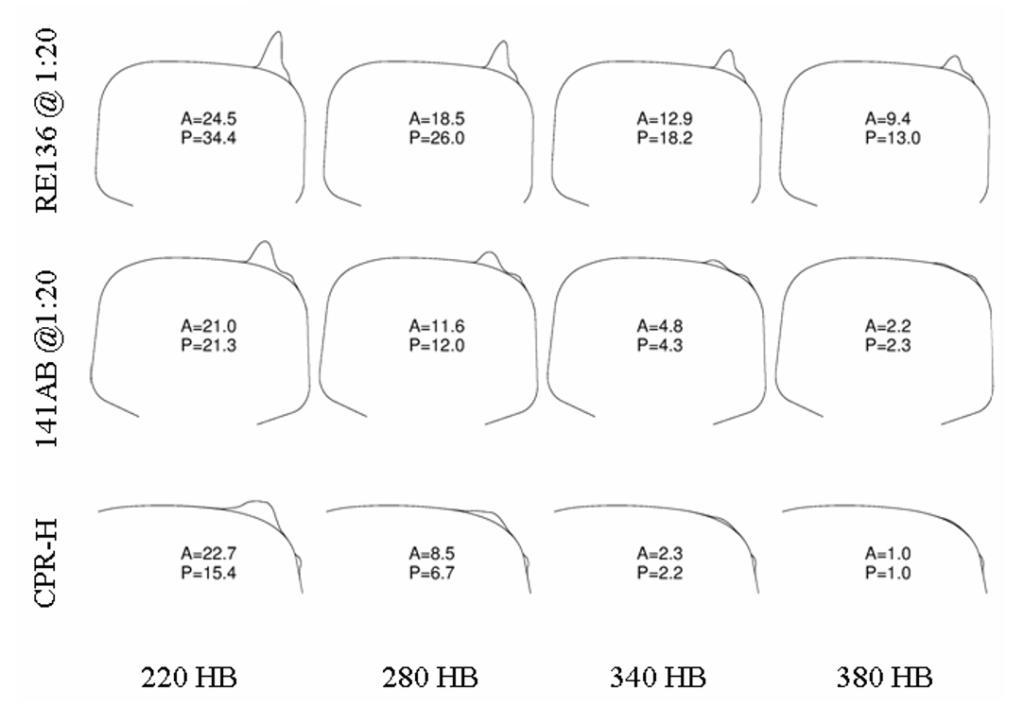
Improved rail profiles can also help reduce RCF. Figure 7 shows the results of a quasi-static pummeling simulation where only contacts exceeding the shakedown limit are accumulated. The accumulated damage for three different rail profiles having three different hardness are plotted. The CPR-H profile shows a significant reduction in these forces. “Just by changing the rail profile you can reduce the amplitude of the contact stress and the probability of rolling contact fatigue,” Magel said. The figure also shows how improved profiles are synergistic with harder rail steels; the best combination is the CPR-H at 390 HB.
Rail grinding also plays an important role in managing RCF. In addition to being the means by which new rail profiles are implemented, regular preventive grinding is an effective way to arrest the exponential growth of RCF cracks. “10 or 20 MGTs is typically the ideal time to grind,” Magel said, in terms of balancing metal removal and RCF management. Grinding like this effectively resets the crack growth curve (see figure 8).
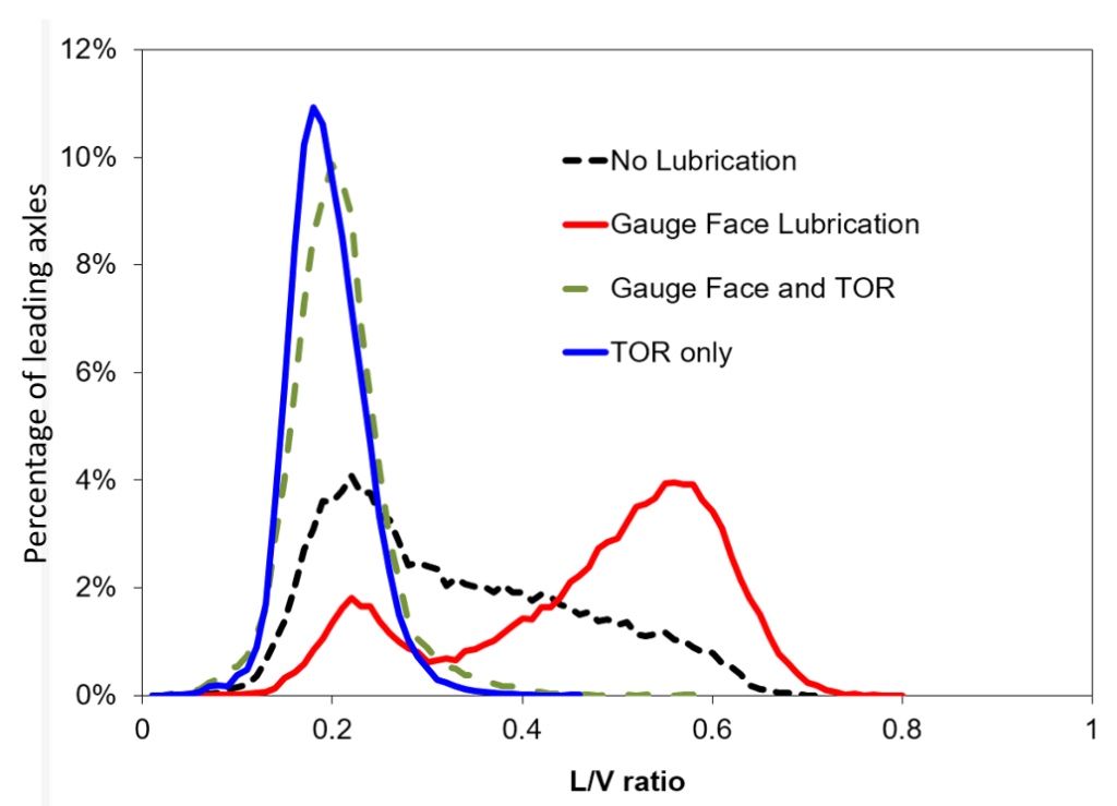
There are also less-invasive ways to help mitigate RCF. Top-of-rail (TOR) friction management shifts the population on the shakedown graph by limiting surface traction and reducing lateral forces. This is also synergistic with improved wheel/rail profiles and harder steels, Magel said. Figure 9 shows an Amtrak study showing the effects of gauge-face lubrication and TOR on lateral over vertical forces (L/Vs). “Laboratory and field testing has shown that TOR, whether combined with lubrication or not, gives a dramatic reduction in L/Vs,” Magel said. This in turn leads to less shakedown exceedance.
Truck suspension also synergizes with improved wheel and rail profiles. A flexible suspension, combined with the improved steering of matched wheel/rail profiles reduces the yaw angle and wheel angle of attack, which reduces creepage, which reduces the likelihood of RCF, Magel said. The M-976 truck, adopted in 2003 by the AAR, has shown to improve wheel life by 18 % to 24% versus standard three-piece trucks.
Finally, wheel and rail metallurgy play an important role in mitigating RCF in addition to the add-on effect of their synergy with other wheel/rail conditions. The K in the shakedown chart is the shear strength of the metal; an increase in hardness translates to an increase in RCF resistance.
And RCF doesn’t just affect rail. The wheel experiences the same contact stress, and the same type of RCF damage. The interventions that mitigate RCF on the rail also benefit the wheel. ”They’re part of the same system,” Magel said. Although there are more measurement devices available to detect and quantify RCF in rail, several companies are currently developing machine vision and electromagnetic systems that are wheel-specific.
Last, but not least, effectively mitigating RCF requires a systemic approach. Strategies that work well alone work better in concert with each other. As the ability to quantify RCF continues to improve, so does the ability to intervene earlier and more cost-effectively. These mitigation techniques have proven their effectiveness on heavy-haul and transit systems around the world. As these techniques are optimized, so too is the wheel/rail interface.

Jeff Tuzik is Managing Editor of Interface Journal.
This article is based on a presentation made at the WRI 2023 Heavy Haul conference.

