Mitigating Transverse Defects and Reducing Non-testable Areas: Grinding Strategies at CSX
By Jeff Tuzik
Transverse defects are among the most costly and dangerous rail defects that freight railroads contend with. Across all Class 1 railroads, transverse defects are responsible for roughly 31 percent of broken rails system-wide; so mitigating the growth of transverse defects and detecting their presence via internal flaw detection is of critical importance. To that end, CSX has recently made significant improvements to its rail grinding program that have both reduced the number of TDs and TD-caused rail breaks on their system, and improved their ability to detect them.
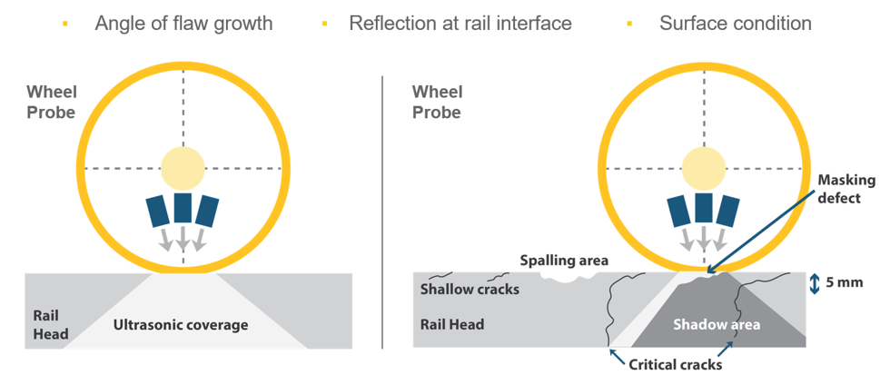
Transverse defects can be initiated in two ways: surface-initiated and subsurface-initiated. In both cases, standard ultrasonic rail flaw detection tools can detect the defect before it reaches a critical point and potentially causes a rail break. However, poor rail surface conditions due to shelled, spalled, corrugated (SSCs) rail or rolling contact fatigue (RCF) can reflect and distort ultrasonic signals, preventing detection by conventional Ultrasonic Testing (UT) inspection systems, and making the section “non-testable”. This combination of factors makes transverse defects a particularly vexing problem, Dan Hampton, CSX Director of Contract Services, told delegates at the 2024 Wheel/Rail Interaction Conference.
In 2016, we had a combined total length of 30 miles of non-testable locations. By 2023, there were less than 1000 feet in 21,000 track miles; a 98% reduction.
Dan Hampton, CSX Director of Contract Services
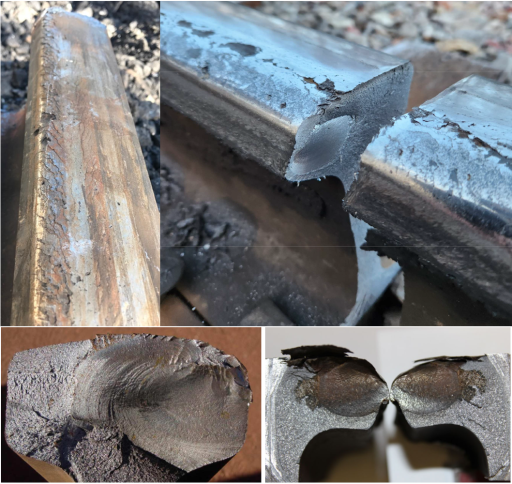
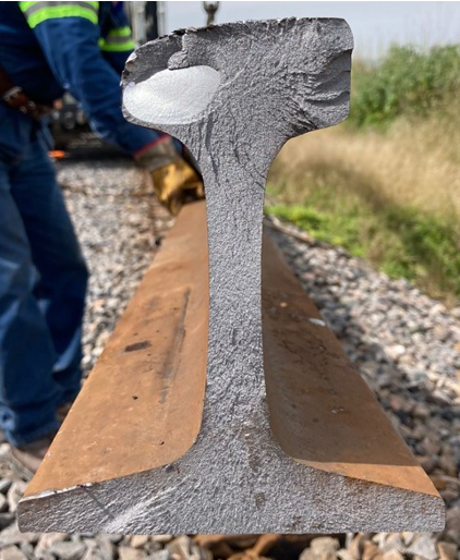
Surface-initiated TDs, which are typically initiated by cracks formed by RCF, are typically controlled through rail grinding. Left unaddressed, RCF-generated cracks will propagate. A combination of thermal and mechanical stresses can drive the cracks deeper into the rail, potentially initiating a transverse defect (and broken rail) of the type seen in Figure 1. Surface-initiated TDs can be particularly dangerous because RCF and SSCs on the rail surface can interfere with ultrasonic detection, effectively occluding the transverse defect (or any other defect beneath the RCF).
Rail grinding does double duty by removing the damaged layer of the rail surface: It arrests the development of RCF-generated cracks before they propagate deeper into the rail and allows for effective UT testing. Rail profile grinding is done to bring the rail into a desired profile shape that mitigates excessive contact stresses on the gauge corner; in the case of TD mitigation, the target is typically a light 2-point contact profile that works well with a variety of wheel profiles. “Since freight railroads don’t control wheel maintenance on freight cars, rail profiles have to accommodate a wide range of wheel profiles and conditions,” said Frank Stillman, Vice President of Service Excellence at Sperry Rail Service, and Hampton’s co-presenter.
Subsurface TDs typically begin with the development of a subsurface shell at the gage corner due to high contact forces between the gauge corner and wheel flange. Over time, continued high stress causes the subsurface rail material to crack and collapse along a shear line thus forming a shell. Once a subsurface shell has begun to develop, it can quickly (invisibly) propagate deeper into the rail. The mechanism of propagation in most such cases is the repeated bending and thermal stress of the rail under load, Stillman said. As rail steel quality and metallurgy/micro-cleanliness has improved over time, manufacturing defects and internal flaws are responsible for a shrinking portion of rail breaks, while those initiated by TDs (both surface and sub-surface-initiated) have grown in proportion.
A shell that has already formed can’t be ground out of the rail; it must be cut out and replaced with a plug rail, said CSX’s Dan Hampton. But rail grinding does play an important role in alleviating the high-stress contact conditions that caused or contributed to the previous shell formation.
RCF Mitigation and Improved Ultrasonic Fidelity
Mitigating the risk of TD development and controlling RCF so that rail surface condition doesn’t interfere with ultrasonic testing requires a grinding program that takes into account varying crack growth and wear rates throughout the system, Hampton said.
CSX began to overhaul its rail grinding program in 2016, initiating a process that both curtailed transverse defect development, and improved the accuracy of ultrasonic rail flaw detection. For example, most tangent sections typically only need to be ground every 50 to 70 MGT, while sharp curves may need to be ground every 15 MGT, he said. In CSX’s case, 90% of the network has 3-degrees of curvature or less. As such, their preventive grinding cycle is based on RCF crack growth rate on 3-dregree curves. For the small population of sharper curves on the network, CSX allocates the resources for additional grinder passes, but adheres to the same MGT-based cycle.
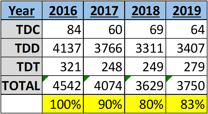
In 2016, CSX introduced a second grinding team to its network. Based on historical data on RCF development, wear rates, and MGT, Hampton’s team developed and implemented optimized grinding cycles and routes and focused on targeting RCF at the gage corner. Under this new regime, the occurrence of transverse defects fell by ~19% (see figure 3). Additionally, their TD-caused broken rail incidence fell from ~20% to ~13% (of all broken rail causes). There are plans to further refine the metrics used to calculate these grind cycles. “The MGT-based RCF crack growth figures we’re currently using are an average, but with a surface evaluation system like an eddy current device, we could know the exact crack growth of any given location,” Hampton said.
Another aspect of the grinding program that CSX continues to optimize is the target depth of cut, or metal removal, for a given track segment. Based on data collected from broken rails with transverse defects indicating gage-corner cracking as the defect initiation point, CSX modified their grinding protocol to increase depth of cut if gage-corner RCF is present at any severity level. Gage-corner RCF is typically found on high rails in curves, and these rails’ service life is typically limited by lateral rather than vertical wear; “so the additional ‘wear’ due to metal removal has a negligible effect on rail life,” Hampton said. Additionally, CSX now grinds the entire curve body based on the worst-case gage-face RCF found in the curve.
The combined effects of ensuring that preventive grinding cycles are met, and of aggressively targeting gage-corner RCF have yielded impressive results. Since these protocols were implemented in 2020, CSX has seen the TDD population fall by 37%. Over this same period; TDDs as a percentage of all rail service failures fell from 20% to 13%.
In addition to improving rail condition by mitigating RCF and reducing transverse defect formation, CSXs grinding improvements have also improved the accuracy of ultrasonic flaw detection, which requires a smooth, clean surface for optimal signal transmission between the ultrasonic transducer and the rail. In addition to blocking or otherwise interfering with ultrasonic transmission and effectively hiding potential internal defects, poor surface conditions due to SSCs or RCF can interfere with ultrasonic testing results in other ways, too. “Sometimes a surface defect looks just like a transverse defect and sometimes a transverse defect looks just like a surface defect,” Sperry’s Frank Stillman said. “Surface conditions also affect the repeatability of inspections, and these variations make it impossible to accurately track the progression of internal defects over time.”
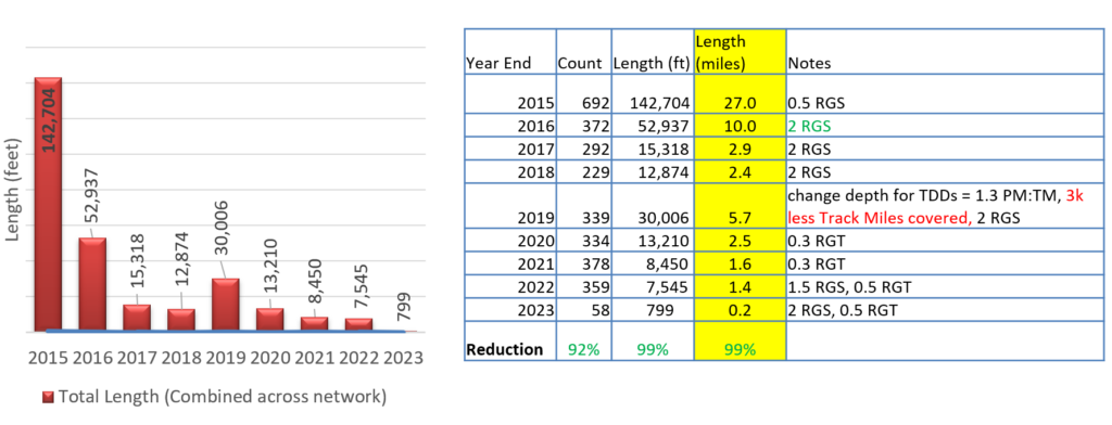
Since CSX began to overhaul its grinding program with respect to transverse defect mitigation, their efforts have also significantly reduced the number and size of non-testable locations throughout their network. In 2015, prior to the improvements Hampton detailed, there were 692 non-testable locations measuring a combined 142,704 feet on the network. By 2023, there were only 58 non-testable locations measuring a combined 799 feet (see Figure D).
Hampton noted that the small spike in non-testable locations in 2019 corresponds with the increased depth of cut implemented that year which resulted in the grinders covering less of the network overall. “Once we caught up to our new grinding cycle, we got over that hump and the SSCs continued to trend downward,” he said.
Another part of the effort to reduce non-testable locations was to catalogue these locations by type. Figure 6 shows the number of non-testable track feet by category from 2014 to 2018. The categories are:
- Specialty assets
- Curves
- Rail surface quality and fatigue
- Bridges
- Tangents within 200 feet of a spiral
- Sidings
- Steep grades and absolute signals
“Switches and road crosses made up the majority of [non-testable] locations, and we found that we just weren’t grinding them with adequate frequency,” Hampton said. Before the grinding began in 2016, CSX had access to only one specialty grinder for six months out of the year to address these locations. CSX has since devoted more resources to specialty grinding and to better leveraging the flexibility of their mainline grinders. This includes significantly more combined operations in which a mainline grinder works alongside a specialty grinder for added flexibility. These modifications to the grinding program have proved particularly effective; as Figure 6 indicates, virtually all categories of non-testable locations were drastically reduced or eliminated by 2018.
The optimization of CSX’s rail grinding program is an ongoing project. Rail grinding itself is a balancing act; defect removal and profile shape must be balanced against metal removal. The allocation of grinding resources must be balanced against other operational and logistical constraints. In reducing both the number of non-testable locations and the population of transverse defects in their rail, CSX has struck a balance between the theoretical and practical aspects of rail grinding to develop a program that has yielded tangible — remarkable, in fact — results.

Jeff Tuzik is Managing Editor of Interface Journal.
This article is based on a presentation made at the 2024 Wheel/Rail Interaction Heavy Haul Conference.


