Measuring With Eddy Current: Gage Corner Cracking and the Magic Wear Rate
By Ryan McWilliams and Eric Eberius
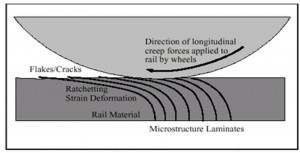
Figure 1. The ratcheting strain deformation of the rail — as longitudinal creep forces are imparted by tractive effort, braking, and longitudinal steering forces — causes plastic deformation and propagates crack initiation.
Gage corner cracking (GCC) of the rail from rolling contact fatigue (RCF) is a dangerous and costly form of rail damage. Unfortunately, it’s also notoriously difficult to measure. And as GCC becomes more prevalent on rail systems around the world, accurate measurement is an immediate concern for both safety and performance.
Origin of Gage Corner Cracking
RCF occurs due to a ratcheting of each loading cycle (wheel pass) which causes the rail to plastically deform, eventually forming an incipient crack. If a rail wears faster than RCF generates cracks, that rail eventually needs to be replaced due to wear. If a rail experiences excessive RCF-initiated surface cracking, it needs to be replaced even if it hasn’t reached the wear limit.
Most infrastructure owners prefer a balance where rail life is maximized by periodically grinding out the crack-generating damage caused by RCF before the cracks propagate deeper into the rail. Failure to do so can be disastrous; Figure 2 shows the remnants of a catastrophic rail failure from the British Rail System’s Hatfield derailment in 2000. The close-up in Figure 3 shows an example of the extreme GCC that led to the failure.
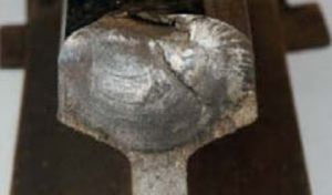
Figure 3. A close-up of severe gage corner cracking from one of the above rail sections. Image source: Train Derailment at Hatfield, A Final Report by the Independent Investigation Board, July 2006.
Factors which cause GCC are a common topic of debate and discussion. The basic premise is that longitudinal steering forces (which are a function of lateral wheelset shift), lateral wheel/rail forces (which are a function of axle angle of attack), and vertical forces (from static weight and dynamic movement) all play a key role. Additional variables such as lubrication, wheel/rail profiles, track curvature and alignment, cant deficiency, primary truck yaw stiffness, and system wear, only add to the difficulty of nailing down the origins of GCC.
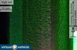
Figure 4a. Example of GCC on the high rail. Image courtesy of Virtual Vehicle via Metro Network Vienna.
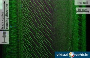
Figure 4b. Example of GCC on the low rail. Image courtesy of Virtual Vehicle via Metro Network Vienna.
In the not-too-distant past, the operating conditions and metallurgical properties at the wheel/rail interface caused rail to wear at a rate fast enough to wear away most surface cracks. Today’s materials are much harder and they last longer, meaning surface cracks are not necessarily worn away and may propagate deeper into the rail and initiate GCC.
Figures 4a and 4b show RCF-initiated cracks that have moved into the gage corner. The images also highlight the variation in gage corner crack pattern between the high and low rail.
Management
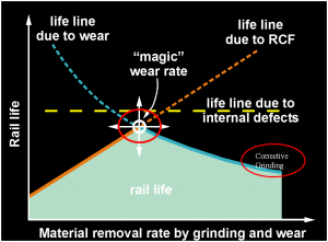
The most common regimen for GCC management is the implementation of a grinding or milling program which removes just enough rail material to eliminate the cracks but not so much that good rail is ground away. There is a term aptly named the “magic wear rate” (see Figure 5) which refers to the rate of wear (both natural and artificial) required to optimally manage RCF. It is a concept which recognizes that when there is no wear, the rail can fail due to RCF (should the contact stress be high enough and should the ratcheting plastic deformation be present), but when there is excessive wear, rail life is unnecessarily wasted. This is the basis for preventive rail grinding/milling programs worldwide.
While grinding/milling programs are increasingly prevalent RCF management tools, the ability to ensure proper measurement has lagged behind. Since there has been no way to tell just how deep a series of cracks might be, grinding programs have been more “art” than science — relying heavily on local knowledge and educated trial and error.
New eddy current inspection devices may be able to help bring measurement and management closer together. Although eddy current technology has historically had difficulty measuring accurately in the field, there are now a few case studies that bolster the viability of using this inspection method to detect GCC.
Measurement
A manually pushed eddy current system has been under development for some time. Deutsche Bahn (DB) performed both laboratory and field studies to determine crack behavior as well as to validate the accuracy of eddy current inspection technology. The studies, along with other tests in Europe and North America, resulted in DB’s approval in March 2011 of the “Manual Eddy Current Test Instrument WPG D340,” i.e., the Draisine.
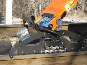
The Draisine is a 4 channel eddy current instrument with adjustable probes set to measure surface cracks on the gage corner and rail head. Surface and near-surface cracks are measured, that data is then stored, and processed in real-time. The Draisine also provides information including flaw location and calculated damage depth, which can aid in grinding assessments and operations.
The Draisine’s accuracy was initially validated by measuring a cut section of rail with known crack depths, which were verified through visual inspection and the use of a hand inspection probe. The Draisine was then used to measure the cut section of rail in the field. DB’s tests between 2008 and 2012 have shown that the Draisine generally measures within 10% of the actual crack depth as verified by alternative means.
Early in 2012 DB approved the full production version of the Draisine for use on all tracks throughout the country, and now requires network-wide eddy current inspections. Two measurement trains test the entire network twice a year; in sensitive areas such as curves, the inspection interval is more frequent. In areas where defects are known and must be closely monitored, the test frequency is monthly or as needed, via the hand pushed Draisine.
Draisine in North America

Figure 7a. High rail pre-grind data covering 100-200m of section with damage depth ranging from <0.5mm to >2.0mm

Figure 7b. High rail pre-grind data covering 200-300m of section with similar damage depth observed.

Figure 8b. After the first grinding pass (note: Draisine was re-calibrated just prior to the 1st grinding pass due to the extreme level of surface damage observed at this location).
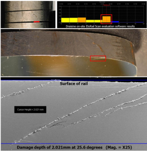
Figure 9: The top image shows the correlation between the laboratory and Draisine crack measurement. The middle image shows the crack after polishing. The bottom image is an electron microscope view quantifying crack angle and damage depth. The areas within the red boxes reference the same section of rail at different levels of magnification.
North American testing and trials began early in 2011 at a research and test facility in Pueblo, Colorado. Further testing took place in 2012 and 2013 at the Pueblo facility as well as the Union Pacific (UP) western mega site and the Norfolk Southern (NS) eastern mega site for pre- and post-grind RCF/GCC measurement evaluation. Norfolk Southern provided another location where pre- and immediate post-grind measurements were taken to ensure that the inspection device could “see through” surface grinding marks. The following statistics are from the NS Virginia Division test site:
• Curvature: 6 degrees
• Super Elevation: 3 1/2 in.
• Rail size: low 141RE, high 136RE
• Rail installation date: low 2003, high 2010
• Ties: wood
• Fasteners: Victor 8×18 in. plates with Pandrol clips
• Ballast: granite
• Annual Tonnage: 41 MGT
• Typical number of powered cars: The vast majority of traffic is eastbound loaded coal trains with two six-axle locomotives pulling 120 cars (no DP or helper).
• Average train speed through the curve: Timetable speed 35 mph, observed actual speed 30 – 34 mph
• Braking / Accelerating: Steady pull due to level grade
• No repeating annual maintenance requirements or issues.
Pre-grind data was gathered from both high and low rails over a 400m section of curves including two bridges that had not been ground for some time due to fire hazard concerns (See Figures 7a and 7b).
The grinding train was scheduled to make five passes on the low rail and two passes on the high rail based on the NS grinding plan (which takes into account profile objectives and significant RCF; although “significant” has not been historically quantifiable). To further evaluate the measurement system, a section of low rail was identified and measurements were taken immediately after each of the five grinding passes.
With each pass of the grinding train, measurements indicated a slight reduction in the RCF damage depth. The measured crack depth is shown in Figures 8a-d. Even after the fifth pass, some minor RCF damage was visible. If it were not for the eddy current inspection system, there would be no way of knowing how deep these residual cracks were — whether they were insignificant or dangerous.
Initial results indicated that the Draisine was able to accurately measure the surface cracks and was able to “see through” the surface irregularities caused by the grinder. Further validation was required to confirm the actual crack length, angle and depth.
Subsequent testing of four short sections of rail were measured with the Draisine and then removed from track and sent to the NS lab where crack length, angle, and depth were measured. The top inch of each section was removed, and cross-sections were polished for evaluation under an electron microscope. Measured crack length, angle and corresponding damage depth were compared to the eddy current measurements.
Figure 9 shows that the Draisine measured damage depth to be 1.95mm, which compares favorably to the damage depth of 2.021mm measured in the lab. The other three sections were evaluated in the same manner and field measurements were found to be within 10% of the lab results.
Future Work
Tests in Europe and North America indicate that eddy current inspection systems can be reliably utilized as a pre- and post-grind management tool to accurately measure surface crack length — whereby crack depth is calculated based on a verified crack angle. Systems such as the Draisine can provide a greater level of confidence, and confirmation, that grinding is properly managing RCF.
Additional evaluation and validation tests are ongoing on North American Class 1 railroads through the International Collaborative Research Initiative (ICRI). International Engineering, along with various partners, is developing higher speed versions of eddy current inspection technology which are being fit to both high-rail and cart-based platforms to allow for more seamless integration into typical maintenance operations.
The ICRP (International Collaborative Research Initiative) is addressing this subject in detail. Research personnel from around the globe are coming together to share experience, data, and resources. More information on this subject can be found at RailAdvisor.
![]()
Ryan McWilliams is Chief Technical Officer at International Engineering.
Eric Eberius is National Sales Manager at Rohmann LP.


