
New Approaches to Dynamic Wheel Force Measurement
by Jeff Tuzik
The mechanics of wheel/rail interaction are in many ways at the core of railroading and the defining characteristic of how a train gets from here to there. Because rail typically represents a railroad’s largest financial asset, track-related issues are often front and center, even when it comes to wheel/rail interaction. But the wheel is just as important. Advances in wheel impact load detectors and in continuous wheel-condition monitoring are beginning to change the way railroads monitor and maintain their wheels.

In the context of the railroad industry, the wheel/rail pair is defined by two basic characteristics:
- Quasi-rigid rolling contact with low rolling resistance
- Wheelset(s) with an approximately conical tread that promotes self-alignment and self-steering.
These characteristics make railroads a very efficient mode of transportation, and from a theoretical perspective, present a system that is simple to manipulate, and to optimize, Yuqing Zeng, Principal Investigator at MxV Rail, told participants and the 2023 Wheel/Rail Interaction conference. Of course, theory and practice rarely align perfectly.
Defects on the wheel or rail surface can have a significant impact on the wheel/rail system, damaging both vehicle and track. Mismatched wheel/rail profiles can cause excessive wear and rolling contact fatigue, poor vehicle performance, and can lead to potential safety hazards. For these reasons, it’s important to be able to accurately measure forces at the wheel/rail interface from the perspective of wheel, truck, and rail interaction. This is typically done using onboard measurement devices like continuous output instrumented wheelsets (IWSs), or via wayside devices like strain gauges and wheel impact load detectors (WILDs). “Wheel/rail force measurements allow you to make many fast and effective measurements to identify practical problems and solutions,” Zeng said. IWSs have also been used to validate and improve the accuracy of various models and simulations like those used in MxV Rail’s NUCARS modeling software.
Wheel impact load detectors are used extensively in the North American heavy-haul environment. These systems detect the impact or loading force of each wheel passing through the test site and flag wheels that are approaching (or exceed) a threshold that requires intervention. While the network of WILDs in use today has helped to improve industry safety and maintenance practices, there remains room for improvement in wheel condition monitoring, Zeng said. One such area for improvement is in the unification of wayside and onboard wheel/rail dynamics data. Another is the further development of simulations that can better model real-world dynamic forces. “Any improvement to wheel monitoring requires consistent and accurate wheel/rail force information as input,” he said.
Discontinuous and Continuous Measurement
From a technological standpoint, there are a number of ways to measure wheel-force discontinuously — measurements that are taken at certain discrete intervals. The most commonly-used rail strain gauge is based on the shear-force method, also called the differential shear method, Zeng said. This method is easy to implement and generates output data that is independent of the tie and fastener and is stable without additional support. This is the basis for the typical wheel impact load detector. The weakness of this system is that the effective zone of measurement is relatively small, and only accurate near the middle of the crib— typically, the length of the 95% effective measurement zone is less than 200 mm, he said.
Some of the weaknesses inherent in discontinuous wheel/rail force measurement can be countered by the use of continuous measurement devices based on load pads or instrumented tie plates. However, there are weaknesses inherent in this method, too. For example, the output for a given wheel would be affected by the forces generated by the adjacent wheels, Zeng said. To counter this, the rail can be cut at both ends of the measurement zone – this isolates the wheel(s) from those adjacent, but it also creates a discontinuity in the rail that is prone to generating high impact loads. For this reason, such configurations are typically found only in static or low-speed settings like weighbridges and track scales, he said.
An early breakthrough (circa 1980) in continuous measurement techniques proposed the pairing of discontinuous shear-force strain gauge measurement with load pad technology. This effectively extends the effective zone of the shear-force measurement and maintains better wheel force isolation without necessitating a physical cut in the rail, Zeng said. A further refinement of this technique positioned the strain gauges so that the distance between the sensors was less than the wheelbase. “This means there will never be more than one wheel on the shear force and the load pad unit at a time. This means you can obtain the wheel/rail force for each wheel,” he said.
In the early 1990s, the China Academy of Rail Sciences used this technique to improve the accuracy of high-speed track scales and to develop a train performance detection system (TPDS) to monitor hunting on high-speed lines operated by China Railway (CR), Zeng said.
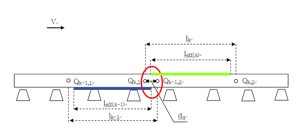
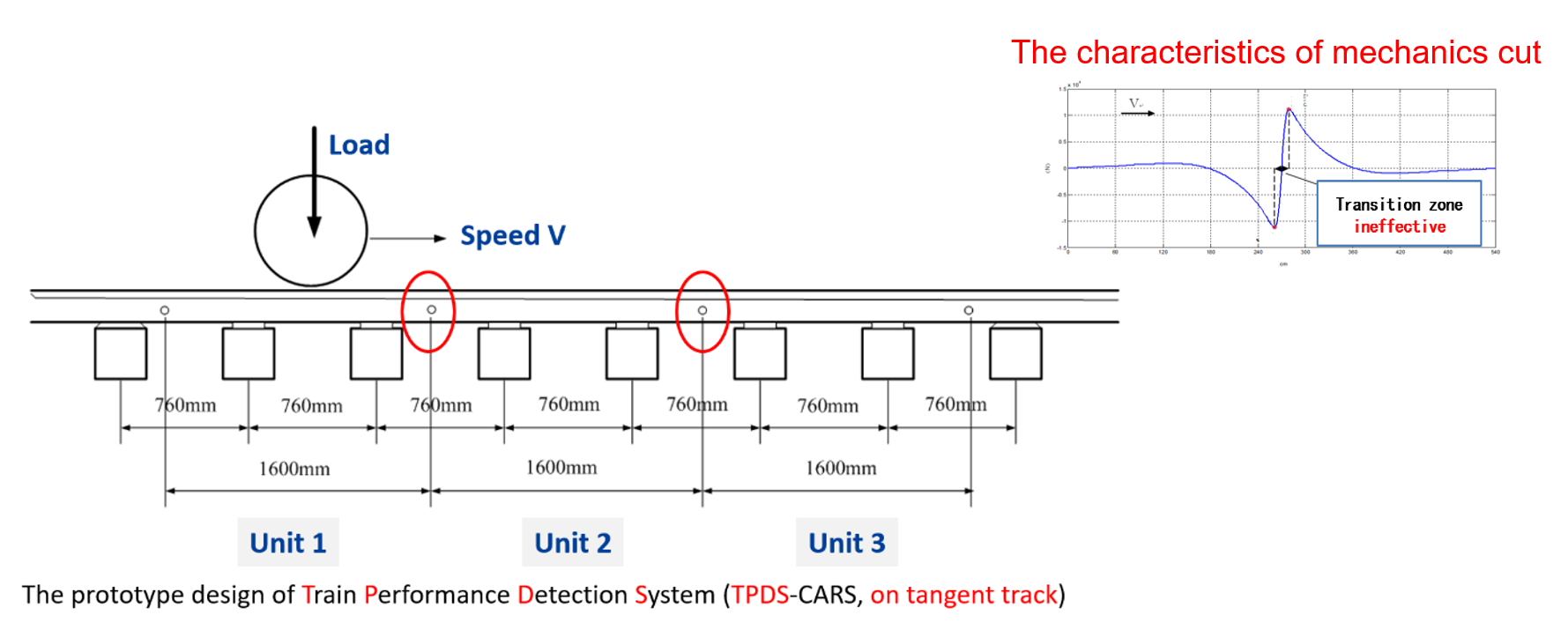
Figure 1 illustrates the basic design of CR’s earlier-model TPDS. In the case of this design, however, there are regions (circled in red) in which wheels pass through a transition zone that can’t properly measure rail shear force. These “dead zones” made up approximately 11% of the TPDS when it was first implemented, Zeng said, making it a “quasi-continuous” measurement system. Full continuous measurement remained the goal for several reasons; first, it would allow for accurate measurement of vehicles with different wheel diameters, and second, it would allow the TPDS to reliably measure wheel circumference, he said. In this case, the solution was fairly simple: the addition of a strain gauge inside the dead zone to effectively make the valid areas overlap (see figure 2).
These overlapping full-continuous measurement systems have proven to be effective, and able to measure a wide range of wheel/rail / vehicle dynamics such as weight in motion (WIM), overload, imbalance, hunting, wheel surface defects, and journal bearing failure. But they are also quite costly and difficult to maintain. As a result, their use is typically limited to specialized test tracks, like the Siemens Test and Validation Center Wegberg-Wildenrath, Zeng said.
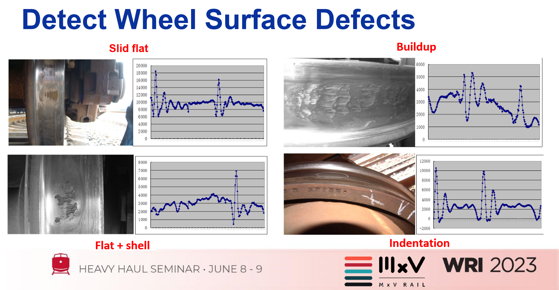
The success of these systems inspired Yuqing Zeng, prior to his work with MxV Rail, to develop an approach to solve the continuous measurement strain gauge gap issue (as shown in figure 1) without requiring additional hardware. This approach, dubbed the Composite Unit Method, uses algorithms to infer “dead zone” data based on adjacent strain gauge, and underlying load pad data, Zeng said. Data generated by this composite unit method can, like in overlap-type TPDS systems, also be used to detect specific wheel surface defects like skid flats, shells, and out of roundness based on their measured characteristics. Figure 3 shows some of these defects and their respective composite unit signatures.
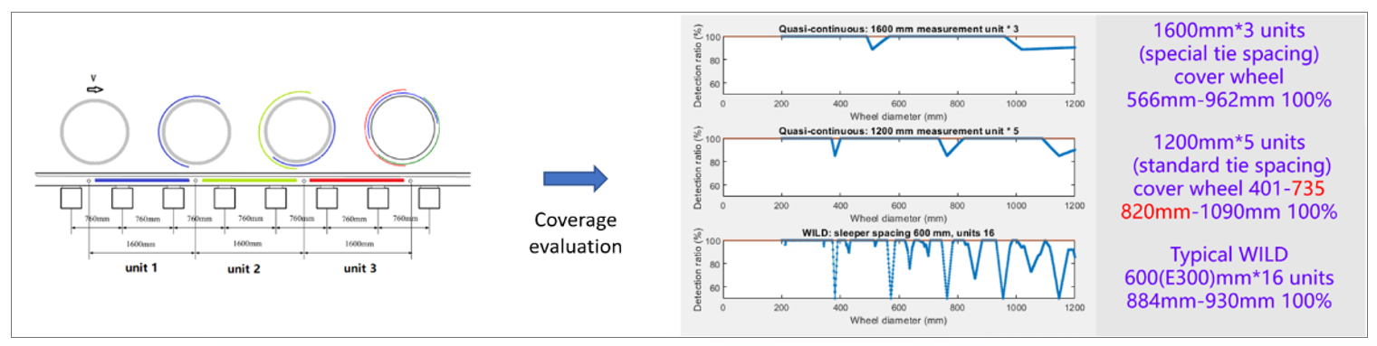
Another benefit of continuous measurement technologies versus discontinuous systems (like WILDs) is that the entire circumference of each wheel can be measured in a shorter test site (see figure 4). “Continuous measurement technologies give you 100% coverage of the wheel, enhancing the effectiveness of wheel and vehicle monitoring,” Zeng said. These systems also provide constant and consistent data that can be integrated with other condition-monitoring data for more in-depth analyses. One example of the kind of in-depth analysis that this data makes possible is assessment of wheel-break risk.
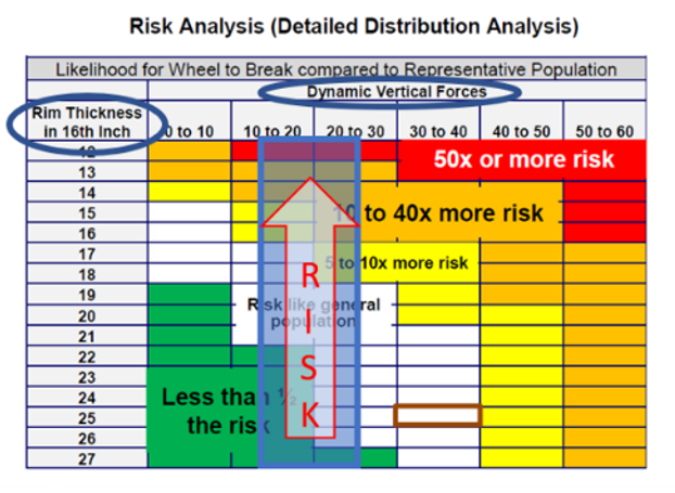
Figure 5 shows the relationship between rim thickness, dynamic vertical forces and wheel-break risk compared to a representative population. Continuous measurement systems can be used to determine wheel circumference, and thus rim thickness, in addition to providing data on dynamic forces — giving a full snapshot of wheel-break risk, in this example. Similar methods can be used to assess the severity of polygonal wheels (out-of-roundness) and their associated hazards. “Discontinuous measurement technologies like traditional WILDs may detect a polygonal wheel, but depending on the frequency of the rotating out-of-round (OOR) wheel, it’s very likely to miss it instead,” Zeng said.
Another Approach

Other wayside measurement devices take a different approach to measuring parameters like wheel out-of-roundness and lateral stability/hunting propensity by way of equivalent conicity (EC). Mermec, for example, has developed several optical/laser-based continuous measurement devices capable of performing many of the same functions as the TPDS systems that MxV Rail’s Yuqing Zeng detailed.
Calculating equivalent conicity requires a number of data points on various wheel and track parameters. These include: left and right wheel profile, back-to-back distance, wheel diameter and diameter difference, rail profile and track gage. “A single wheelset with a high EC value is unlikely to cause hunting, but multiple wheelsets [in a consist] with high values are a strong predictor of hunting,” Enrico Betterle, Product Manager of Wheelset Monitoring Equipment and Data Analysis at Mermec, said at the WRI conference. This highlights the importance of capturing data on every wheel that passes through the wayside unit, and ensuring that there are no “dead zones.”
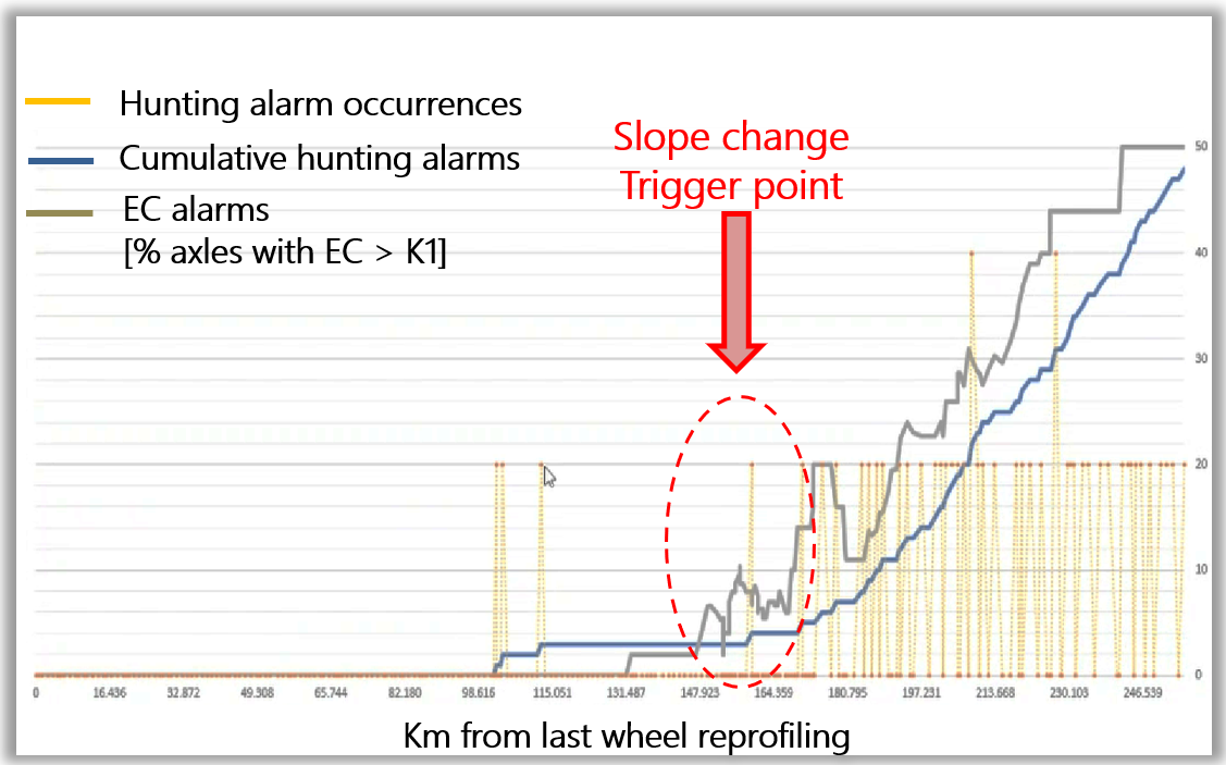
Based on this information, Mermec developed a hunting prediction indicator (see figure 6) based on the percent of wheelsets with EC values exceeding a given threshold (based on operating speed and other operational parameters). This predictive indicator has been validated by one case study in 2022; additional studies are currently underway, Betterle said.
Mermec has also applied its optical wayside system to monitoring wheels for early signs of out-of-roundness. There are many ways to measure OOR wheels, including force detection/ WILD systems like those detailed by Zeng, contact-probe systems like underfloor wheel lathes, and machine vision tread-imaging systems. One drawback of force detection/WILD systems when it comes to OOR measurement is that if a defect occurs outside of the contact band of the wheel, the system can’t detect it, Betterle said.
An alternative method under development by Mermec employs an optical profile-based method to gather in-service OOR data. This method is based on a statistical, cumulative buildup of full circumference data over the course of multiple passes through the inspection unit, Betterle said. Each wheel that passes through the unit is measured at 4 random points around the circumference; after 15 passes, 70% of each wheel has been measured; after 20 passes, there is 80% coverage, and after 45 passes there is greater than 95% coverage. Because this is a statistical method, the final OOR value is the maximum value detected over a certain number of inspections. “The limitation of this approach is that the measurement unit must be installed somewhere that sees very frequent train passages,” Betterle said. The strength of the system, on the other hand, is that measurement covers the entire transversal tread profile, making it easier to locate defects occurring outside the contact patch. Betterle also cautioned that at this stage, this method should not be considered a substitution for established OOR detection practices, but rather an additional dataset that can be integrated with other wheel condition data.
A New WILD
In addition to the ongoing refinement of continuous measurement systems like those developed by MxV Rail and Mermec (and others), the railroad industry has also sought development and validation of alternative WILD technologies in recent years. A June 2021 update to AAR S-6101: Detector Validation and Calibration Requirements specified onboard measurement of wheel impact loads using instrumented bearing adapters. This specification is based on AAR member experiences with carbody dynamics testing and based on the assumption that reaction at the bearing adapter should equal force at the wheel/rail contact patch.
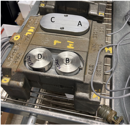
Figure 7 shows the layout of the instrumented bearing adapter, which features four parallel load cells. After adding half of the axle weight, the sum of the load cells represents the wheel load, Zeng said. Each instrumented adapter was connected to one high-impact wheel, and the test consist was made up of both loaded and unloaded cars.
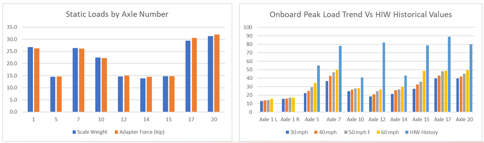
Test results (see figure 8) showed that axle static loads (adapter force in kips) matched scale weight within approximately 5%, but that onboard peak loads were well below the high-impact wheels’ historical WILD data. To determine the reason for this large discrepancy, a free boundary 4-degrees-of-freedom was built. “Based on the model, you can obtain the transfer function from the force on wheel/rail contact patch to the bearing adapter,” Zeng said. This data showed that significant damping was occurring somewhere in the system. One possible method of correcting for this is to modify the transfer function (from wheel/rail force to bearing adapter force) based on a specific damping factor. But the transfer function is dependent on many vehicle characteristics, and this method provided inconsistent results, he added.
This is an ongoing project and MxV Rail continues to refine their bearing adapter measurement concept based on their experience with IWSs. One step that could help set a baseline for measurement and validation of the instrumented bearing in the future, is to engineer a specific high-impact wheel whose specific characteristics could be benchmarked with IWS and wayside measurements, Zeng said. This would help eliminate some of the variables that complicated initial testing. It’s also important to determine the extent to which bearing adapter force data corresponds to the likelihood of component damage and failure rates in the way WILD data does.
Wayside measurement systems have become increasingly sophisticated over the years. While the traditional WILD continues to be an invaluable tool, the development and implementation of continuous wheel/rail force measurement technology promises a tremendous amount of useful data on wheel condition and on wheel/rail interaction. While such systems may never fully replace the reliable WILD, it seems likely that they will continue to expand their niche as they become more sophisticated and more economical.

Jeff Tuzik is Managing Editor of Interface Journal.
This article is based on a presentation made at the WRI 2023 Heavy Haul conference.