
Implementing Rail Grinding and Wheel/Rail Interface Optimization Programs on Heavy Haul and Transit Systems: Lessons Learned
by Jeff Tuzik
Rail grinding continues to evolve. Though still a standard part of the track maintenance and optimization toolkit, grinding programs look very different than they did when grinding programs first became commonplace in the 1980s. Preventive grinding, for example, has gone from niche to mainstream; it’s the target for most transit and heavy haul systems, on small commuter lines and massive mining networks alike. Grinding machines have changed, too. Their greater size and capability, when coupled with advanced measurement systems and performance metrics, enable more precise and efficient grinding operations. Lessons learned from rail grinding programs around the world, where theory and practical application have met, sometimes messily, sometimes serendipitously, have shaped and refined modern grinding programs.
Eric Magel, Principal of EM-WRI Consulting Inc., and former Principal Engineer at the National Research Council of Canada (NRCC), has seen a lot of rail grinding. His career with the NRCC roughly spans the period from 1990 to 2020 and took him to freight and transit properties around the world. “The 90s was an exciting time to be involved in rail grinding,” he told delegates at the 2024 Heavy Haul Wheel/Rail Interaction conference. “The JK rail profiles [named after Joe Kalousek, his mentor and the recipient of WRI Seminars’ first Worth Award] were becoming more widely adopted in North America, there was debate over conformal versus two-point contact, and premium rail steels were becoming more prevalent,” he said. In addition, preventive rail grinding was gaining traction as an efficient long-term grinding strategy.
South American Transit: Systemic Approach
Early in his career, Magel, working with Stuart Grassie—Principal, Rail Measurement Ltd and Stuart Grassie Engineering Ltd and recipient of Wheel-Rail Seminars’ 2024 Worth Award—was involved in a rail grinding project on a South American transit system. The system was new, running light axle loads, and riddled with wheel/rail interaction problems. There was severe wheel polygonization (corrugation of the wheel treads), heavy corrugation of the rail (causing noise and vibration issues and contributing to broken components on cars) and deep-seated shells, primarily at the gage corner in the high rail in curves. “Even with very light axle loads, shells were popping out of the gage corner.”
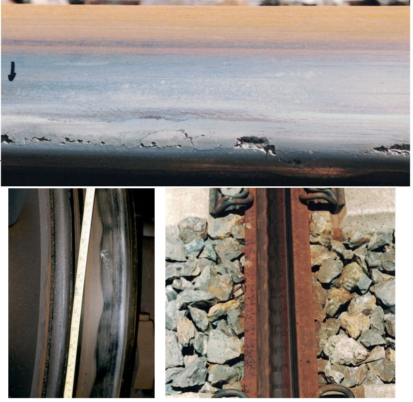
There are two primary avenues for addressing the root cause of corrugation, Magel said. It can be done by correcting the wavelength-fixing mechanism via damping, decoupling components, or otherwise changing the predominant resonance; or by introducing wear-reducing wheel/rail profiles and/or friction modifiers. “Going after the wavelength fixing mechanism works sometimes, but it’s often very expensive,” he said. “And you have to remember that there will always be resonances in the system; you might deal with one and find another that’s a problem.” In the case of the South American transit system, there were also the gage corner shells, which are inherently unrelated to the wavelength fixing mechanism, to contend with. For these reasons, fixing the damage mechanism was the optimal choice, Magel said.
Unfortunately, the transit system’s only rail grinder was a reciprocating grinder. This type of grinder operates by sliding grindstones back and forth longitudinally along the rail. “It didn’t remove much metal, but over time it could smooth out corrugation,” he said. However, the grindstones were shaped such that they were also flattening the rail, giving it an almost squared-off profile. A profile like this, particularly in a high rail, makes for very severe contact conditions between the wheel flange root and the gage corner, leading (in this case) to the formation of deep-seated shells, he said.
Lessons Learned
Common though it is, corrugation is complicated. There are many contributing factors, and the root cause is not always clear, Magel said. And because there is always resonance in the system, and always some form of damage mechanism (like RCF, or wear, for example), corrugation is nearly inevitable unless the system has been specifically designed, from the ground up, to suppress it. Another takeaway from this case is that it is possible to grind improperly. “The reciprocating grinders were removing corrugation temporarily, but the flattening of the rail, in fact, contributed to its rapid reformation, and caused the incidental shelling at the gage corner. This is why it’s necessary to look at the whole system, not just the immediate problem. “When you make any change [to the system] you have to consider knock-on effects that may manifest elsewhere, either immediately or over a long period of time.”
Australian Mining Railway: Corrective Grinding
Another project took Magel to an Australian mining railway to investigate rail surface conditions, including dipped welds, RCF and hunting. There was significant RCF, he said, but the railway wasn’t particularly concerned with it. “Because of the very dry operating environment, wheel/rail friction conditions were very high. In these conditions, RCF cracks typically only grow to a relatively shallow depth; there’s not enough ambient moisture to be regularly compressed into the cracks and further propagate them” he said. It’s also important to note that the railway didn’t have a regular grinding schedule, but rather ground on an as-needed basis, based on track inspector reports.
Some of the issues affecting the railway were directly related to their operations—specifically, running loaded trains downhill, slowly, to the unloading facilities and running empty trains back to the mine at high speed. This led to conditions in which the rail profile favored the downhill, loaded trains while the fast, light uphill trains experienced significant hunting. Though in fact, Magel said, the actual rail profile was not optimal for either operating condition.
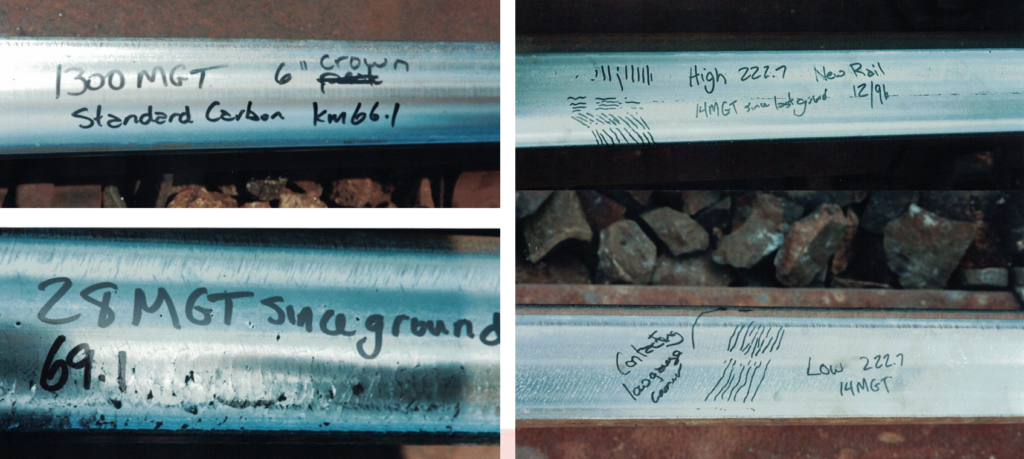
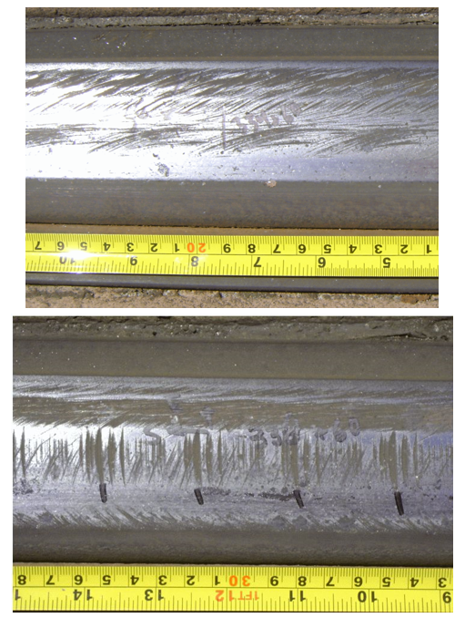
Figure 2 shows (top left) a recently-ground rail on the railway with an accumulated 1300 MGT of traffic. The photos to the right show the high and low rails 14MGT post-grind, and the photo bottom left shows the same rail 28 MGT after grinding; significant gage corner RCF is already visible.
On the one hand, Magel said, it’s hard to argue with success. “[The mining railway] was running heavy axle loads on lower-quality steel and getting very good life out of it despite the RCF.” Even so, the presence of RCF is never a good sign; it indicates that the rail profile is not performing optimally, and therefore not providing the benefits to wear rate, steering, hunting suppression, and RCF resistance that it was designed for, he said.
Lessons Learned
Designed rail profiles only work if they’re maintained, which ties into another lesson from this case: preventive grinding is more efficient than corrective grinding, Magel said. Preventive grinding, which is scheduled at regular intervals, aims to mitigate defect growth (such as RCF), control exponential growth rates, and maintain rail profiles to their design/optimal condition. Preventive grinding makes more-frequent, lower-effort interventions rather than the more typical grinding programs that make less-frequent higher-effort interventions when defects are far along into their exponential growth curve. This is a common and commonly known practice today, but it wasn’t always. “We had to make quite an argument on this particular project to make the case for preventive grinding.”
BNSF: Preventive Grinding
When the Burlington Northern and Santa Fe railroads merged in 1995, their grinding philosophies and practices were put to the test. Prior to the merger, BN had spent several years getting its grinding program and its rail into a preventive state, Magel said. Santa Fe, on the other hand, did not grind—owing in part to the relatively dry, low curvature conditions on much of their network. The merger provided no additional grinding budget, and there was additional pressure to reduce or remove grinding altogether, as part of a “no grind” movement within the industry at the time.

Under these conditions, the merged BNSF began, within a short time, to see accelerating rates of rail surface damage, including gage corner shelling on high rails and top of rail shelling on low rails, crushed heads, surface initiated transverse defects and dipped welds, as well as evidence of wide gage, fastener damage and other signs of poor rail condition, Magel said.
Determined to prove the efficacy of preventive grinding but lacking the resources to implement a large-scale program, BNSF, working with the NRCC, developed a plan to preventively grind and monitor a small test site in their Pacific Northwest territory. The logistics of implementing the project with a single grinder proved untenable, so Joe Kalousek, who was the NRC’s grinding guru at the time, suggested adopting a “preventive gradual” approach.
This program called for implementing preventive grinding cycles across the territory without first removing the defects and establishing the design rail profiles, Magel said. Preventive-gradual grinding cycles were based on MGT and curvature: every 20 MGT on sharp curves, 40 MGT on mild curves, and 60 MGT on tangent. The tenets of the program were to:
- Maximize spark hours and grinding efficiency by working with operations to optimize track time.
- Perform only a single grinding pass (with a few limited exceptions); this meant slowing down, if necessary, to maximize metal removal.
- Focus first on reducing the stress state by applying optimal profiles, and then target damage and defect removal in subsequent grinding cycles.
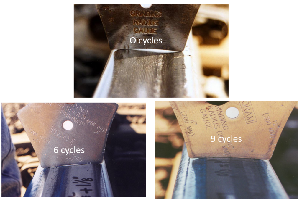
Figure 3 shows the progression of this program on a crushed low rail at 0, 6, and 9 cycles, representing roughly two years of grinding. “You can see we’re not worrying about the damage left behind, but we’re progressively catching up on the shape. That’s why we call it “preventive-gradual,” we’re gradually catching up to get the rail to a preventive state,” Magel said.
The results of this study1, presented at AREMA 2001, showed that the “preventive gradual” program provided numerous economic benefits, including significantly increased rail life, increased grinder productivity, reduced grinding cost per mile, decreased surface defects and decreased internal defects. “The BNSF team needed to demonstrate to management that grinding was important, and worth doing. These key performance indicators prove it to them in their terms.”
Lessons Learned
There is risk, of course, involved in implementing a large scale and novel program like this. But trying something new and different always involves some inherent risk. That’s why it’s important to monitor as much as possible in order to mitigate the risk and to intervene quickly, if necessary, Magel said. It’s also important to educate the stakeholders so they’re aware of how the program will progress. “We went to several places on the BNSF property and presented the program to all the roadmasters and track inspectors. We told them what we were doing, why we were doing it, and what to expect. We also assured them that we were taking responsibility for the program and that it wouldn’t blow up in their faces.”
Grinding programs are often large, long-term projects that require significant commitment, so, high level support of the program is critical. This means that explaining the program and its benefits and telling the story through data and key performance indicators is also important, Magel said.
Canadian Pacific: More Knock-ons
In the early 2000s, Canadian Pacific (CP) initiated its “100% effective lubrication” program, which involved equipping a territory with state-of-the-art gage-face lubricators and lubricants and monitoring their effect on multiple metrics like rail wear, and fuel consumption. The program was quite successful, but there was an unexpected knock-on effect, Magel said.
“Because there was no gage-face wear and no gage-corner cracking in the test territory, the grinding crew started changing things they shouldn’t have,” Magel said. The rail profiles were designed to be ground to 45-degrees on the gage face, but because the grinding crew saw no visible wear or defects there, they started grinding only to 26-degrees on the gage face. This created a stress raiser at that location on the gage corner. And because of the effectiveness of the 100% effective lubrication program, that corner didn’t wear away.
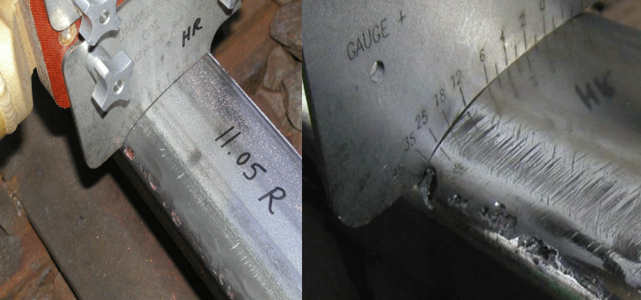
Instead, deep-seated shells formed. Figure 4 shows an example of this shelling and a template on which the 26-degree hatch mark is visible. The solution was to return to grinding all the way to 45-degrees and to remove at least 0.2mm of metal in the process, Magel said. This solved the immediate shelling problem. But, again, there was an unexpected knock-on effect.
Another consequence of the optimized lubrication program was that excess lubricant was no longer spilling onto the top of rail, leaving the top of rail much dryer than it was previously. This led to high wear and lateral forces at the low rail, forcing the wheelset against the outer rail such that the grinding to 45 degrees was insufficient to stop gage corner shelling. The program was amended to grind down to 60 degrees on the gage face and CP embarked on a “100% effective friction management program” that added top of rail friction management applicators to reduce lateral forces.
Lessons Learned
As in the case of the South American transit, this case illustrates the complexity of interaction at the wheel/rail interface. When conditions change, or when knock-on effects come to light, it’s important to stop and re-evaluate the grinding approach, Magel said.
Sound Transit: Surface Roughness and Fine Tuning
It’s possible to grind improperly. A 2010 review of rail conditions at Sound Transit found that the previous grinding cycle left a very rough grind signature (see figure 5). “On a transit system, rough grinding stays around for quite a while. Because of light axle loads and low MGT, it is possible for that roughness to remain for years,” Magel said. At Sound Transit, the grind signature, combined with the typical operating speed of trains on the affected track excited a resonance that caused a spike in vibrations at 63hz (force density level / ⅓ octave band measurement)
The initial plan to remove and “correct” the grind signature was to employ a two-step grinding process. The first step was to use standard “coarse” grindstones to remove defects and correct the rail profile. The next step was to switch to finer, softer stones (of which several grindstone formulations were tested) and apply multiple polishing passes to get a clean and relatively signature-free rail surface, Magel reported.
Advanced Rail Management (now Global Rail North America), working with Sound Transit, experimented with multiple combinations of stones, grinder speeds, and grind module pressures to dial in a combination that provided a balance of surface finish smoothness and grinder productivity. In this case, a single-step process using medium-grit stones provided the best results with the least compromise; Implementing these new surface roughness thresholds effectively reduced systemwide noise and vibration and eliminated Sound Transit’s problems with clips breaking due to excess vibration.
Lessons Learned
Fine tuning the grinding program is not only possible but necessary to ensure the best results. The grinding machine, rail profiles, grinding frequency, operating speeds and stone types can be selected in order to work most efficiently and effectively for a given railroad with its specific rail surface problems, budget restrictions and logistical constraints.
Rail grinding continues to change. Technologies for quantifying RCF are increasingly used in conjunction with grinding programs to ensure defect-free conditions. Rail milling is making inroads in North America as a complementary rail maintenance technology. Rail grinders are increasingly precise and increasingly automated. Advances in metallurgy and the increasing prevalence of premium rail steels have influenced the relationship between wear and RCF, the design of optimal profiles, and the frequency and amount of grinding. Improvements in friction control are also changing the equations. As railways, researchers and grinding practitioners contend with these changes, there will be new lessons to learn; sometimes the easy way, sometimes the hard way.

Jeff Tuzik is Managing Editor of Interface Journal
This article is based on a presentation made at the 2024 Wheel Rail Interaction Heavy Haul conference.
- J. Stanford et al, “Transitioning from corrective to preventive rail grinding on the BNSF railroad” The 7th International Heavy Haul Conference: Confronting the Barriers of Heavy Haul Technology, June 10-14, 2001, South Brisbane, Australia ↩︎