Profile Optimization in the Urban Rail Context
By Edgar Fischmeister, Markus Ossberger, Roman Pongracz
and Paul Mittermayr • April, 2007
Measurement is an essential aspect of optimizing wheel/rail interaction on urban transit systems. After extensive research and development work, Wiener Linien, the Vienna (Austria) Urban Transit System, implemented an integrated wheel/rail measurement system that enabled the railway to closely monitor wheel/rail contact and optimize wheel/rail profiles on the system.
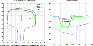
Wiener Linien is the first urban transit provider to utilize two measurement cars for regular rail measurement runs across its entire network. One measurement vehicle is suited for metro track testing; the other is designed for measuring grooved, or girder, rail for embedded streetcar track testing (see Figure 1). High-precision laser measurements are taken every 0.5 meters to capture the shape of rail head from the outer to the inner edge, and to calculate head wear. The measured part of the rail web and the upper part of the base are used to identify the rail type. (The underside of the rail head typically cannot be “seen” by the laser beams.) In the case of grooved rail, only the head surface, the groove and the guide flange can be measured. In addition to these measurements, a circle is approximated at the inner flange of the rail head. This diameter is used to estimate wheel wear and to calculate the contact geometry, as well.
Evaluating the Data
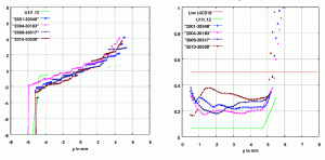
Following measurement of the Wiener Linien system, data was processed (with checking and two-dimensional smoothing) and used to analyze wheel/rail interaction. First, the theoretical profiles were examined to highlight the contact geometry potential. For this purpose the wheel profiles were laterally offset from their center position, while the wheel/rail contact was calculated iteratively. This enabled the railway to determine the regularity of contacts on both the rail and wheel — an important aspect of wheel/rail interaction on the system since spot contact on one of the profiles leads to concentrated wear and a rapidly changing in-service profile in the same spot. Computation also showed rolling radius difference as a function of lateral displacement (see Figure 2), where shifts in contact points and striking of the flange against the rail head can be seen. The equivalent conicity for certain amplitudes resulting from the rolling radius difference was also calculated. A standard requiring that conicity does not exceed 0.5 was established. Conicity that is too low is also unfavorable, as it provides an insufficient turning angle for proper sinusoidal motion.
The location and distribution of contact points under (cyclical) lateral subsidence helps identify the wear tendencies of interacting (wheel/rail) components. The contact patch locations are used to compute equivalent conicity, which helps characterize stability on tangent track, whereas rolling radius difference affects performance on curves.
While optical rail measurement has been performed for years on standard open-track railways, Wiener Linien’s streetcar measurement car is the first to monitor the profile quality of grooved rails. However, owing to the fact that grooved rails are built into the street, only part of the rail head (running surface, groove and check) can be measured. Nevertheless these profile data provide important parameters such as wear surface, depth and width of groove, and the radius of the running edge. With this information, rail profile conditions can be monitored and maintenance planned throughout the network.
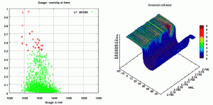
The left part of Figure 3 shows the results of a measurement run on metro line U1. The conicity is shown as a function of the gauge in a scatter diagram. The conicity is within the specified range, except for a small section. The illustration indicates that tight gauge leads to higher conicity. Unfavorable profile pairings and stresses may exacerbate these adverse effects.
Wiener Linien varied the rail profiles to improve contact geometry. By distributing the contact patch locations, the railway was able to keep the equivalent conicity within a favorable range and improve rolling radius difference for better curve negotiation. Modifying the rail head radii provided a slightly wider gauge where desired to improve rolling radius difference.
As a result of regular measurement and automated rail-profile analysis, which includes wear, head radii and equivalent conicity (see Figure 3), rail conditions can be evaluated, grinding programs can be planned, and the remaining life of rail in each track segment can be estimated.
Wheel Measurement
Just as measurement of rail conditions represents an essential aspect of managing wear, measurement of wheel conditions provides the ability to monitor wheel tread and flange wear, and the damage mechanisms that affect rail and wheel service lives. And just as the use of mechanical gauges to check rails in track have given way to automated, laser technology, the mechanical gauges and templates used to check wheel geometry in the shops have been replaced by automated, precision measuring devices.
The wheel flanges on the leading wheelset of the “pushed drawbar wheels” at portal 1 have by far the highest wear rate of the whole vehicle. Compared to the wear of the wheel flanges of the leading wheels of conventional tram railcars, the average wear is approximately 40% higher. This dramatic wheel wear shown through MiniProf measurements during long-term tests of ultra-low-floor (ULF) vehicles with self-steering independently rotating wheels (built into articulation portals), led to mandatory periodic inspection of wheels on all vehicles every 10,000 kilometers. This, in turn, led Wiener Liniento purchase automated wheel profile measuring equipment that collects wear data in an integrated database that is used to plan maintenance requirements on the system.
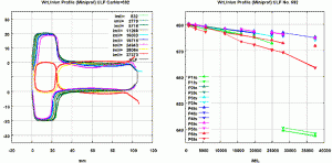
Figure 4 shows the change in the entire profile shape of individual wheels. Since trams have doors on the right hand side only, the door-side portal (right) is pointing upward and the window-side portal (left) is pointing downward with reference to the original profile. The left side of Figure 4 shows the evolution of the tape circle diameter of all individual wheels (P1 fs = portal 1 left side, P1 ts = portal 1 right side; down to portal 6) as groups of curves at the times of individual measurement. Ranging from an almost unworn state (with a diameter of 680 mm and a kilometric performance of 832 km) to conditions after almost 40,000 km of service, wheels on the first and last portal are clearly subject to greater wear. The wheels at the first portal required re-profiling after approximately 28,000 km. Owing to the unfavorable profile shape, it was necessary to remove almost 30 mm to reestablish the original profile. The different rates of wear of the individual wheels (diameter plotted above kilometric performance) can be seen on the right side of Figure 4.
Overall experience has shown the benefits of obtaining consistent wear over the full width of the wheel and the rail. Controlled wear reduces re-profiling requirements and reduces hollowing of the wheel tread. The elimination of hollow wheels has been shown to extend the life cycle of switches and crossings and reduce plastic flow on the rail head.
![]()
Edgar Fischmeister (Dipl.-Ing.) is Head of Tracks Department, Wiener Linien; Markus Ossberger (Dipl.-Ing. Dr.), is Maintenance Process Manager, Tracks Department, Wiener Linien; Paul Mittermayr (Dipl.-Ing. Dr.) is Managing Director of BAMM, Roman Pongracz (Dipl.-Ing.) is a Senior Consultant and former Senior Manager at Wiener Linien.
References
Brandau, J.“Einsatz unsymmetrischer Schienenkopfprofile im Nahverkehr.”Dissertation Universität Hannover, 1999. (“Use of non-symmetrical rail head profiles for light rail transit.” PhD-thesis Hanover, 1999.)
Iwnicki, S. (Ed.) “Handbook of Railway Vehicle Dynamics.” CRC Taylor & Francis 2006.
Mahr, A. “Abstimmung der Rad-Schiene-Geometrie mit dem lateralen Fahrzeugverhalten – Methoden und Empfehlungen. ” Dissertation TU Berlin, 2002. Fahrzeugtechnik. Aachen: Shaker Verlag 2002. (“Adjustment of the wheel/rail geometry with lateral vehicle behavior – Methods and recommendations.” PhD-thesis UT Berlin, 2002.)
Ossberger, M., Mittermayr, P. “Messstrategien für den Oberbau im urbanen Bereich.” EI Der Eisenbahningenieur 56(9), 12–16, 2005. (“Measurement strategies for the superstructure of urban rail systems.”)
Pongracz, R. “Radverschleißaspekte im Schienennahverkehr.” Special ETR Austria 2, 729–737, 2005. (“Aspects of wheel wear in light rail transit.”)
TCRP Transit Cooperative Research Program, Report 57. “Track Design Handbook for Light Rail Transit.” Transportation Research Board, National Research Council. National Academy Press, 2000.


