Understanding Stresses in Rails (Part 1 of 2)
By Jude Igwemezie, Ph.D., P.Eng • January, 2007
Rail represents a significant part of any railway’s investment in annual track maintenance. At the end of its useful life, the scrap value of rail can be as little as 15% to 20% of its original cost. Proper management of this precious asset will have a positive impact on the user’s bottom line, operating ratio and net asset value. Understanding the stress environment will help determine the ultimate life expectancy of the rail.
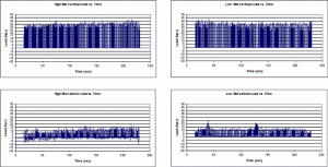
To understand the stresses in rails, it is necessary to establish the loading environment of the rail. We often discuss train wheel loadings, but very few of us have actually measured wheel loading from a train. Figure 1 shows the vertical (two top graphs) and lateral (two bottom graphs) wheel loads measured on both rails under a coal train traveling at 16 mph on a 1% grade and 10-degree curve. (The graphs on the left column belong to the high rail; those on the right column belong to the low rail.) The track speed at the location was 25 mph. The train had two puller locomotives and two pusher locomotives. As expected, there is more vertical load on the low rail than on the high rail. Lateral loads were generally less than 15 kips on both rails, except for the occasional bad actor truck that generated up to 25-kip lateral loadings on the low rail. These loads are then distributed to the track components with reactions generated at the tie locations along the rail. The track also deforms under these loads.
Load Distribution in Track
There are four types of load distribution in track: vertical, lateral, longitudinal and torsional. These distributions can be treated individually and their effects summed. In this article, we will deal only with the vertical and lateral load distribution.
Load distribution in track has been a subject of study since the creation of the railway system. Though it may appear otherwise, a single wheel load is not carried by a single tie, nor is the wheel load between ties carried by the two adjacent ties. The implications of this statement are far reaching in that they impact the design and assessment of track components. Understanding load distribution allows for better assessment of the response of track components to wheel loading.
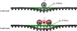
Figure 2 shows the vertical loading from one wheel and one truck on a typical track system. As can be seen, the load in each case is distributed over several ties. The adjacent wheel in the two-axle system clearly increases rail deflection — by 16%, in this case. In fact, under varied track support conditions, the increased deflection can range from about 10% in frozen track to 30% in mush track. With regard to the behavior of the rail, Figure 2 shows that the rail is deformed with an upward concavity. It also shows that the rail is in reverse bending with a downward concavity about three ties away from the wheel. These reversing deformations play into the total stress and fatigue cycles that the rail is subjected to. Overall, vertical load distribution and deformation of track is influenced by the tie spacing, ballast (track support stiffness), rail size and axle spacing. Lateral loading is also distributed over several ties, but the type of rail fastening and torsional rigidity of the rail play a significant role in the distribution. (Note that there are no lateral loads applied to the track in generating the displacements shown in Figure 2.)
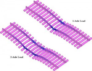
Lateral load distribution, such as is shown in Figure 3, is affected by the lateral stiffness of the track and the amount of shoulder ballast that is available to resist the lateral load. The number of ties that participate in the distribution of the lateral loading is similar to the number of ties that participate in the distribution of the vertical load. Very often, lateral loading to the rail causes torsional distortion of the rail (shown in Figure 4). Because the rail is weaker in torsion than in vertical or lateral bending, torsional distortion occurs only one or two ties away from the axle load point.
Rail Stresses and Fatigue
Stresses and wear are directly related to the life of the rail and susceptibility of the rail to fatigue damage. If the stress is external, such as contact or dynamic stresses, the rail will wear or fracture. If the stress is internal, such as residual or thermal stresses, it can accelerate the growth of fatigue defects, again causing fracture. A three-dimensional Finite Element (FE) analysis can be used to rationalize these different stresses. Figure 4 depicts the stress distribution in rails from the one- and two-axle loading (as shown in Figure 2). As can be seen, there is a concentration of stresses at the wheel locations. This means that assessment of the stresses in rails and the capacity of the rail to carry load depends on what is happening in the immediate vicinity of the load. It also means that the use of simple bending stress computations will be inadequate in assessing the stresses in rails. A detailed look at the stresses in rail in the vicinity of the load, and how wear influences the distribution, is warranted.
Contact and Dynamic Stresses
As the name suggests, contact stresses arise as a result of the wheel contacting the rail. The magnitude of the stress depends on the applied forces, the material and the geometry of the contacting surfaces. If the forces are applied perpendicular to the contacting surfaces, the maximum contact stresses do not occur at the contact surface but occur in a region located inside the two bodies and just below the contact point. If a horizontal force, such as friction, is introduced, the maximum contact stress can be pulled to the contacting surfaces.
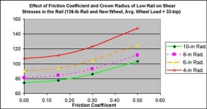
Figure 5 shows the relationship between the maximum shear stresses, the coefficient of friction and the radius of the top of the low rail computed for the same wheel diameter and contact radius.
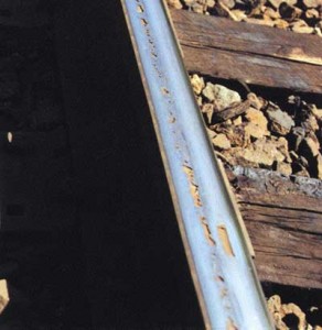
As shown in Figure 5, increasing the coefficient of surface friction increases the shear stresses, as does decreasing the radius at the top of the rail. Some amount of friction is necessary, however, to ensure that damage starts on the top running surface of the rail, rather than starting sub-surface (as shown in Figure 6). Where there is high friction between the two surfaces, the damage will start at the surface of the low rail as shown in Figure 7.
What controls the magnitude of the contact stress? Wheel/Rail contact, of which there are two primary types: one-point and two-point contact.
One-point contact occurs when the wheels and rails wear themselves into a conformal shape, or when the false flange of the wheel contacts the top of the low rail. In reality, conformal contact is never found in ordinary revenue freight service with interchange of vehicles between roads. This is because the rail wears to the average of all the wheel profiles that run over it. Similarly, the wheels wear to the average of all the railhead profiles and the wide- or tight-gauge conditions that they run over. In some cases, such as with transit systems, mining railways or railroads with captive consists, conformal wheel/rail contact can be achieved. Nonetheless, conformal contact leads to hollowing of the wheels, vehicle hunting and the formation of corrugations.
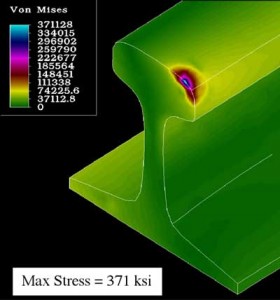
One-point conformal contact conditions at the gauge corner of high-rail occur when the vertical and lateral loads are applied at the same point. This gives rise to very large stresses (see Figure 8 on prior page) and leads to the formation of gauge corner shells and detail fractures (see Figure 9).
The one benefit of conformal contact is that it provides rolling radii difference on curves by allowing the wheel on the high rail to ride close to the throat (with a bigger radius), and the wheel on the low rail to ride on the field side of the wheel tread (with a smaller radius).
This creates the same effect as rolling a cone. This condition improves steering around curves and reduces the lateral forces generated during curving. But, it increases wear at the gauge corner of the rail. The magnitude of the contact stress (371 ksi) is three times the yield strength of premium rail (typically 120 ksi).
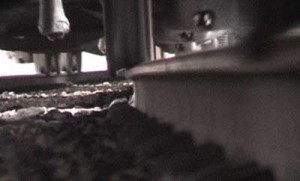
The wheel/rail contact point on the low rail, which always sees one-point contact, is also important. The wheel/rail contact point should occur as close to the center of the wheel running tread as possible (as shown in Figure 10). Good track gauge and a stiff truck system are required for this to occur.
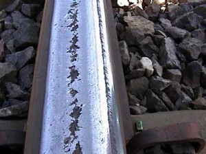
When the track gauge is wide or the truck warping resistance is weak, the wheel contacts the rail at the field side of the wheel where the false flange is formed. False flange contact will also occur if the flange that is riding the high rail is thin and the entire axle is displaced towards the high rail. Rail damage from false flange contact is shown in Figure 11.
Two-point wheel/rail contact occurs only on the high rail, and is more desirable because it reduces the concentration of stress at the gauge corner of the rail. In this case, the wheel tread makes contact on top of the rail while the flange makes contact with the gauge face of the same rail head. This form of contact is achieved by grinding off the material at the gauge corner of the rail head. Two-point contact usually leads to truck warping. It can also generate high lateral forces, which, however, can be dramatically reduced with proper lubrication of the top of the low-rail.
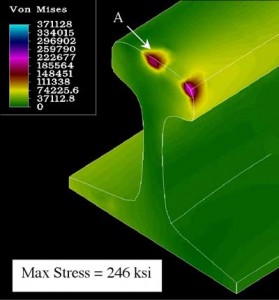
Figure 12 shows typical Von Mises stress in the head of the high rail from two-point contact with the wheel. (Loadings similar to those shown in Figure 8 were used to obtain the stress in Figure 12.) As can be seen, the maximum stress is reduced by 33%. So, while each type of contact has its merits and demerits, two–point contact produces lesser stresses and reduced high rail damage.
![]()
Dr. Jude Igwemezie is President of Applied Rail Research Technologies (ARRT), Inc.

