Pre-engineering the Wheel/Rail Interface
By Rob Caldwell • October 2010
The wheel/rail interface is a complex system – one that benefits greatly from careful pre-engineering. There are significant benefits from properly addressing the wheel/rail interface, and serious consequences from allowing the interface to govern itself. While there are examples of both pre- and post-engineering scenarios, there are more instances of the latter.
Pre-engineering means making informed decisions based on engineering analysis during the design phase, when changes can be made economically. Solid engineering and planning during the design phase is far more cost effective than reactive maintenance and problem solving after the system is up and running.
The specific goal of pre-engineering is to reduce downstream costs by taking into account and eliminating or minimizing common issues that may arise over the life of a system. Infant mortality is one such issue that can be eliminated. This includes premature wheel or rail replacement due to unusually rapid gauge-face or flange wear, surface damage or corrugation development, wheel flats from sliding, rapid tread hollowing — anything that fails soon after entering service. Infant mortality is most common when vehicles and track are separately designed and specified. Proper pre-engineering minimizes future service reliability issues, such as shops and maintenance-of-way equipment that may not be able to handle a sudden influx of vehicles or miles of track that need repair, and thus bottleneck the system. The potential for noise and ride quality issues must also be considered during the design phase so that costs associated with mitigating them do not come as a surprise. From inception, the system must be designed with the understanding that certain ongoing preventive measures, such as grinding and friction management, will be necessary. Their costs should be factored in during design.
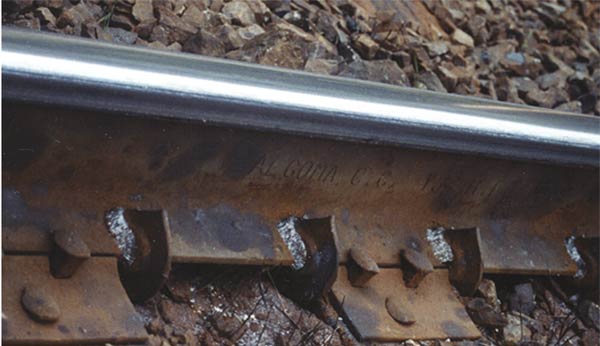
While proper engineering will reduce wear in the wheel/rail interface, wear cannot be eliminated. There are different wear mechanisms at work, but the most problematic for transit systems tends to be adhesive wear between the wheel flange and the gauge corner/face of the rail. Adhesive wear occurs as the asperities between the apparently smooth wheel and rail surfaces weld together under contact then are sheared and torn apart, leaving behind a rough surface and often rail “dandruff” on the tie plates (see Figure 1).
Wear rate reductions of 8 – 20 times are readily achievable with gauge-face lubrication, making it the most effective treatment for gauge-face wear. Use of head-hardened rail can reduce wear rates by 2 – 3 times, compared to standard carbon rail. Proper wheel/rail profile design and the use of flexible bogies can also provide comparable reductions to the damage done by wear. In combination, the effects are synergistic and it is possible to virtually eliminate measurable gauge-face and wheel-flange wear. These solutions are also effective in minimizing rolling contact fatigue.
Rolling Contact Fatigue
Rolling contact fatigue (RCF) can occur on wheels and rail because of the very high contact stresses and shearing action that occurs at the wheel/rail contact. For each contact cycle where the traction stresses exceed the strength of the material, a small increment of fatigue damage occurs in the near-surface material. Repeated overstressing leads to the initiation and propagation of surface cracks that can grow into the material and link together, causing a shell to break out of the surface.
Figures 2a and 2b show examples of RCF on rails from passenger systems that National Research of Canada’s Centre for Surface Transportation Technology (CSTT) has investigated. Figure 2a is from Railtrack (now Network Rail) in England. Rolling contact fatigue on the gauge corner of the rail was the root cause of the Hatfield derailment, in which four people were killed and 70 were injured. Figure 2b shows a shelled rail from a very light axle load system in South America. These photos illustrate that RCF is not confined to freight railroads.
The wheel/rail interface is subject to a great deal of stress. Minimizing stress is not a simple process. Curiously, wheel/rail contact stresses are not overly sensitive to the load between the wheel and the rail. Halving the load reduces the stress by about 26%. Doubling the wheel radius produces a similar effect. Consequently, modifying wheel load and diameter are neither effective nor practical solutions for controlling contact stresses. Wheel/rail contact stresses can be effectively controlled through careful selection of the transverse wheel and rail radii where these bodies come into contact. For example, a wheel tread could be an arc or a taper and depending on the transverse radius of the top of the rail, the contact stress could be damaging to standard carbon rail that is often used in tangent track. A potential solution to this problem could be to install higher hardness steel on tangent track. A more cost effective solution, especially if there is significant wear life remaining in the rail may be reshaping the rail head to reduce the contact stress to a level that is suitable for standard carbon rail. Acceptable contact stress varies for different rail metallurgies, which adds complexity to the task of engineering optimum profiles.
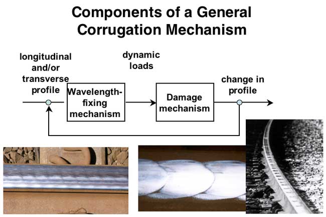
Corrugation is a common problem in the wheel/rail interface. Corrugations are a result of vibrations exciting a wavelength-fixing mechanism that is characteristic of that particular vehicle/track system (see Figure 3). This gives rise to dynamic loads and possibly stick-slip, which act as the input to a damage mechanism (wear, contact fatigue, or plastic flow) acting on the rail. This causes periodic damage, which excites additional vibration at that same wavelength, and the process continues in a feedback loop.
The wavelength-fixing mechanism could arise from the natural torsional frequency of the wheelsets, or a vertical bogie suspension frequency, or a track vibration frequency set by the stiffness of the rail pads. The damage mechanism for transit systems is usually wear.
Unfortunately, corrugation development is hard to predict. It is possible to design against damage mechanisms, but it may be impossible to remove wavelength-fixing mechanisms. Corrugations may still develop in a well-engineered system, but their rate of development can be significantly curtailed through proper design and effectively treated through regular preventive maintenance. Corrugations are self-reinforcing, however, and once they appear they can only be removed by rail grinding or rail replacement.
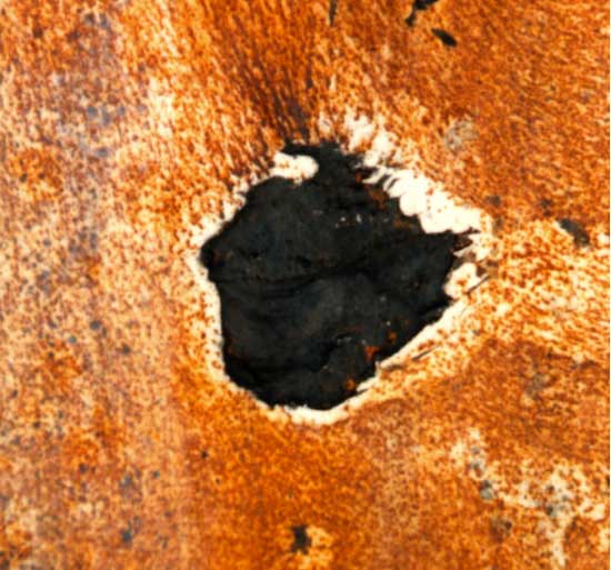
Wheel tread damage is a common symptom of wheel/rail interface problems. The wheelset shown in Figure 4a has slid along the rails, leading to a type of defect known as a spall. (Sliding can result from sticking brakes, or because of heavy braking in low friction conditions.) When a wheel slides, frictional energy flows into the wheel through the contact patch. As soon as the wheel stops sliding, the overheated steel in the contact patch is quenched by the large thermal mass of the wheel. The steel in the contact patch transforms into martensite, which is a very hard but brittle phase of steel. As a result of the skid the wheel has a flat spot at the martensitic area, causing an impact at each revolution. Cracks develop in and propagate through the martensite. When the cracks branch together below the surface, the martensite piece breaks out of the tread, leaving a spall on the wheel surface (see Figure 4b).
Friction Management
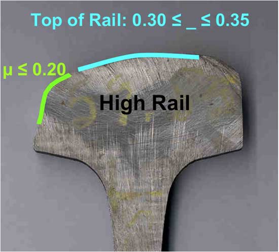
There are two friction zones on rail: the gauge face and the top of rail. Both have different friction requirements. The gauge face of the high rail in any curve where vehicle steering is accomplished through flanging should be lubricated. The gauge face of the low rail could also require lubrication on some tight-radius curves, if back-of-flange contact occurs.
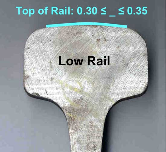
The coefficient of friction (COF) on the gauge face of the high rail (or low rail, if required) should be 0.2 or less in order to minimize wear (see Figure 5a). The COF on the top of rail (TOR) of both rails in curves should be 0.30 – 0.35 in order to prevent loss of adhesion while reducing lateral forces on the curve rails (see Figures 5a and 5b). There are commercially available products that can maintain the TOR COF in this range. TOR friction modifiers can control friction to reduce wear and maintain traction. They have also proven effective in reducing or eliminating wheel squeal and slowing the formation of stick-slip corrugations.
Given the many competing demands in the wheel/rail interface, designing an optimized system can be daunting. Fortunately, with modern technology the effects of profile designs, bogie characteristics, rail hardness and lubrication can all be examined through quasi-static or dynamic modeling. The inputs needed for quasi-static modeling include the wheel/rail profiles, wheel loads, vehicle speed, suspension stiffness, curve radius, superelevation, track gauge/wheel back-to-back distance and COF values. Contact stresses, tangential forces, frictional work and surface damage are the parameters that must be controlled during the design process, and the effects of the inputs on these parameters can be investigated. Figure 6 is a screen capture of the quasi-static curving software developed at CSTT for modeling profile performance, but commercial modeling packages can also be used for this purpose. CSTT also applies fully dynamic simulations using Vampire, NUCARS and SIMPACK to design and optimize wheel/rail and vehicle-track performance, especially for systems where stability, curving and derailment are the dominating concerns.
There are four disciplines that govern the behavior of the wheel/rail interface:
• Metallurgy: the chemical composition and mechanical strength of wheel and rail steels.
• Contact mechanics: the forces and stresses in the wheel/rail contact patch.
• Friction management: gauge-face lubrication and TOR friction control.
• Track/train dynamics: the effects of contact patch forces on movement of the vehicle and track, the position of contact, lateral forces, dynamic gauge widening, instability and derailment.
Manipulation of one of these tools to influence the behavior of the wheel/rail interface can affect the type and severity of damage that occurs. In pre-engineering, it is important to understand what small changes can be made with at least one of these tools to impart a positive, synergistic effect on the system as a whole.
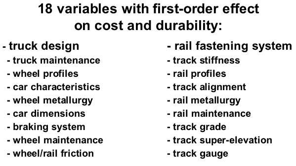
The wheel/rail system includes 18 variables (see Figure 7) that have a first-order effect on cost and durability. The number of variables, coupled with the synergistic complexity of the physics governing them, makes integrated solutions difficult to understand and implement. In addition, most solutions are specific to the system they were designed for and are not easily transferred to other properties.
Despite the complexity, these variables must be addressed during the design/pre-engineering phase. Some of the more common factors that are critical to creating a harmonious wheel/rail interface include:
• Bogie design/stiffness versus track alignment and profile.
• Rail and wheel metallurgy versus contact stresses.
• Tie spacing versus wheel/rail dynamics, rail stresses and ballast pressure.
• Track gauge versus wheel profile and wheelset back-to-back distance.
• Cant deficiency and rail cant.
• Fastening system characteristics versus resistance to corrugation, wheel/rail noise and rail rotation.
• Vehicle characteristics versus track alignment.
• Braking system versus wheel type, wheel wear/fatigue and shunting.
• Target friction performance versus friction management system capabilities and track curvatures.
Proper design and implementation is a matter of matching various design specifications and ensuring that there is harmony throughout the entire wheel/rail system, and not just the stand-alone components. The choice of vehicle characteristics may dramatically affect the required wheel and rail profiles, for example. The selected profiles, track alignment and vehicle characteristics determine the friction management package that should be implemented. The fastening system will be affected by all the previous decisions. And every choice will affect the maintenance strategies and specifications for the system.
As mentioned, there are many cases where insufficient effort was invested in initial design of the wheel/rail interface. The Los Angeles Metro is such an example. When the Metro went into service it did so with a combination of long-wheel base trucks that were poorly matched to the high curvature of the system, lack of lubrication, and poorly matched wheel/rail profiles, which proved destructive to both wheels and rails. Wheels had to be re-trued at 7,000 miles and replaced in as few as 20,000 miles. High speed filming showed that there was wheel lift off, and thus a high risk of wheel climb on the system. To remedy these problems CSTT, in collaboration with other wheel/rail specialists, recommended a number of modifications to the wheel, track and vehicle design specifications, including:
• Harder wheel steels.
• Changes to the truck suspension.
• Solid-stick flange lubrication.
• A higher conicity wheel and matching rail profiles.
By implementing these modifications, the Metro virtually eliminated flange wear and wheel climb, and extended wheel life to 300,000 miles.
The Vancouver Skytrain was an attempt to build a “perfect” system. This highly engineered system included steered trucks, linear induction motors (and thus no powered and only lightly braked wheelsets), small diameter wheels and continuously supported rail laid to perfect gauge. Shortly after Skytrain went into service, it developed wheel squeal, high rates of tread hollowing and flange wear, truck hunting and severe corrugations. The wheels had to be re-trued every 12,500 miles.
CSTT partnered with RESCO Engineering and remedied incorrectly installed truck steering linkages, developed new wheel and rail profiles and recommended the implementation of friction management. These changes dramatically reduced wheel squeal, eliminated truck hunting, and pushed wheel-truing intervals out to 185,000 miles.
There are no short cuts to designing and maintaining an effective wheel/rail interface. It is a complex system that is difficult to optimize. But investing the time and money to get it right the first time yields great benefits. By properly pre-engineering this system, it is possible to avoid many future problems and reactive costs.
This article is based on a presentation made at the 2010 Wheel/Rail Interface Conference in Chicago.

