Implementing an Anti-Shelling Wheel Profile
By Rob Caldwell • October, 2005
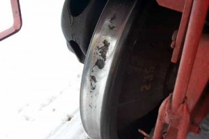 Wheel Shelling has presented serious problems on Canadian railroads in recent years, particularly in winter months. Tread shelling on wheels on Quebec Cartier Mining (QCM) railway’s heavy-haul fleet, for example, reached condemnable limits within one year of use, during the early 1990s. In some cases, this “infant mortality” occurred within as little as 25,000 miles. Once they reached the condemning limit, the wheels had to be removed from service and re-trued to correct the tread damage. The depth of cut required to correct this damage was often large (typically 6/16-inch), which further reduced wheel life.
QCM contracted the Centre for Surface Transportation Technology (CSTT), a technology center of the National Research Council of Canada (NRC), to design a custom wheel profile to combat this problem. The design, known as the QCM-Heumann profile, was implemented during 1995. During the 1995-96 winter season, QCM found that incidences of wheel shelling were reduced by 60% in head-to-head testing with their standard profile, the AAR1B.
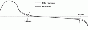
Compared to the AAR1B, the QCM-Heumann profile provides more metal in the flange root, which leads to greater rolling radius difference (ΔR) for any given lateral offset (see Figure 1). This in turn generates a stronger steering moment on the lead axle of the trucks. A stronger steering moment can reduce the angle of attack on the lead axle in mild curves, which reduces the lateral creep forces acting between the wheel and rail. Reducing these creep forces is one way to reduce shelling.
As Figure 1 also indicates, the tread is rolled off with a reversed radius on the field side of the wheel. This feature lengthens the time for the occurrence of tread hollowing and the development of a false flange. A false flange can cause tread shelling through the very high contact stresses that occur when it contacts the low rail. False flange contact can also significantly reduce ΔR for the wheelset, resulting in elevated lateral creep forces acting at the treads of both wheels.
The 1:20 tread slope was maintained on the QCM-Heumann wheel to minimize the risk of hunting. QCM also installed rubberized bearing adapter pads on their ore cars to take advantage of the stronger steering moments, but did not install frame-bracing. This meant that the trucks would be more flexible in yaw and shear than a standard three-piece truck, with higher potential for empty cars to hunt. Hunting ultimately did not occur, however, due in part to the maximum operating speed of 40 mph.
While QCM reaped the benefits of its new wheel profile, wheel shelling had become an epidemic on other Canadian railroads. The seasonal wheel shelling problem, at its worst during the winter months, forced one railroad to raise its Wheel Impact Load Detector thresholds so that its wheel shops were not flooded with shelled wheels that were removed from service because they had exceeded WILD limits. In very cold weather, train speeds were reduced to lower the risk of rail breaks due to high impact forces from shelled wheels.
Rolling Contact Fatigue
Due to the severity of the problem, the Railway Association of Canada (RAC) created a committee to address this issue, and Canadian National (CN), Canadian Pacific (CP) and QCM were the prime participants and sponsors of the committee’s work. The committee determined that rolling contact fatigue (RCF) damage was the primary cause of shelling on the Canadian railroads; martensite was a lesser contributor to the problem.
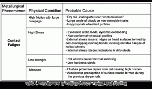
RCF damage occurs when the wheel (or rail) steel is overstressed. The damage occurs in the form of cracks that initiate at or below the surface. These cracks grow and branch together under the surface until the steel above them no longer has sufficient strength to bear the imposed loads. The surface steel can then fall out of the wheel, revealing a shell. The physical conditions which must be present for RCF to develop, and probable shelling causes associated with those conditions are shown in Table 1.
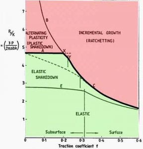
A shakedown diagram, shown in Figure 2, can be used to determine if a particular contact condition will result in RCF damage. The diagram is a plot of the load factor (contact stress divided by the shear strength of the steel) vs. traction coefficient (vector sum of the creep forces in the contact patch divided by the normal contact load). If the point representing the contact condition falls under or to the left (in the green area) of the shakedown limit (represented by the thick black line), no damage will occur. If it falls on the other side (in the red area), an increment of RCF damage will accrue at that location on the tread.
In the summer of 1996, the RAC sponsored the development of a new wheel profile based on the positive results obtained at QCM, and the understanding of the main cause of the shelling. The profile was installed on a portion of the wheels on the CN and CP grain and coal fleets, as they were captive, high-mileage fleets, and results could be quickly obtained.
A total of 732 transverse wheel profiles from both car types were measured in order to obtain a good distribution of the worn shapes that were in operation at both railroads. Using CSTT’s proprietary techniques and software, the profiles were aligned to determine the necessary flange angle, and to create the proper flange root geometry. The tread slope was again maintained at 1:20, although it was shortened compared to the AAR1B profile. The field side of the wheel had a tread roll-off, as per the QCM-Heumann profile. This profile was also designed as a wide-flange wheel, so it could be installed as a new wheel on the fleets.
Improved Steering
The design, known as the Anti Shelling Wheel (ASW) profile, is superimposed onto the AAR1B in Figure 3a. The extra metal in the flange root can be clearly seen, as can the tread roll-off. Both of these features increase the ΔR that can be obtained in curves compared to the AAR1B, although the tread roll-off is a lesser contributor.
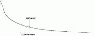
The ASW profile had even more metal in the flange root than did the QCM-Heumann profile, as can be seen in Figure 3b. As a result, the ASW profile would be able to generate even stronger steering moments than the QCM-Heumann profile.
The advantage of a stronger steering moment is that it can somewhat reduce the angle of attack on the lead axle in a truck, which in turn can reduce the lateral creep forces acting in the wheel/rail contact patch. In terms of the shakedown diagram, this results in a lower traction coefficient, which helps to move the contact condition to the left, away from the shakedown limit. The tread roll-off on the ASW resulted in higher contact stresses when in contact with a low rail than would occur with the AAR1B, but not so high as to exceed the shakedown limit. This was viewed as an acceptable trade-off, since the contact stresses were still much lower than those that would result from a false flange contacting the low rail. The effective conicity of this wheel was identical to the AAR1B, for lateral displacements of 6 mm or less from track center. Greater displacement caused contact to occur at the bottom of the flange root area, resulting in higher effective conicity.
The results obtained from CN and CP were different. CP’s ASW profiles showed undamaged treads and minimal tread and flange wear after 150,000 km, whereas CN’s ASW profiles exhibited a band of cracks near the tread centerline. The differences could possibly be explained by the fact that wear on CP’s wheels was evenly spread across the tread because CP was grinding its tangent rail to two separate profiles. Flexible trucks, which can take advantage of the stronger steering moment produced by the ASW profile to reduce angle-of-attack, were also in use on much of CP’s coal fleet. CN was using conventional trucks, and grinding to a single tangent profile which happened to concentrate wheel/rail contact right at the start of the tread roll-off.
Improved Wheel Life
CP processed wear information about the performance of the ASW profile on about 800 wheels and found they were getting an 18% extension in wheel life, compared to the AAR1B. (CN has not produced statistics.) This extension was based on wheels removed for all causes, not just shelling. A statistical analysis determined the mean time between failures (MTBF) for AAR1B wheelsets mounted in conventional trucks to be 199,700 miles. For the same wheelsets mounted in flexible trucks, the MTBF increased to 271,500 miles. The combined MTBF for ASW wheelsets, when used in both conventional and flexible trucks, was 322,800 miles.
On the heels of these very favorable results, CP commissioned the CSTT to develop an improved version of the ASW profile, known as the ASW-Mk2. As seen in Figure 4, this was a narrow-flange profile that had the same flange root geometry and tread slope as the original ASW profile, but the tread roll-off was pushed farther out towards the field side. A narrow-flange design was justified based on the reduced flange wear rate of the ASW compared to the AAR1B. A narrow-flange profile provides an additional benefit: less tread metal needs to be removed during re-profiling to restore the full flange contour.
While data on the ASW-Mk2CP wheels, which CP put into service during the 2004/05 winter, are not yet available, CSTT is cautiously estimating a 25% improvement in wear life, compared to the AAR1B profile. The additional 7% increase in wheel life (compared to the original ASW profile) is attributable to the extra lateral displacement made possible by the use of a narrow-flange design. Such a design can evenly distribute wear over more of the tread and slightly increases the maximum ΔR attainable.
Improving the transverse profile of the wheels is one way to address shelling. However, anything that reduces the load factor and/or creep forces will have a beneficial effect on wheel life. In terms of the shakedown plot, this causes the contact condition to shift downwards and/or to the left, away from the shakedown limit. Friction management and the use of flexible trucks can reduce creep forces. Preventing the development of false flanges and the use of conformal wheel/rail profiles along with higher-strength steels will reduce the load factor.
![]()
This article is based on a presentation by Rob Caldwell at Interface Journaland Advanced Rail Management’s Wheel/Rail Interaction ’05 Seminar.
Rob Caldwell is Senior Engineer, Centre for Surface Transportation Technology, National Research Council of Canada.

