Switch Point Derailments: Is it the point or the wheel? (Part 1 of 2)
By Gary Wolf
No other type of derailment causes as much angst among railroaders as the switch point derailment.
The switch point derailment can take several forms, but it generally boils down to a disagreement between the Mechanical Department that blames the switch point, and the Engineering Department that blames the wheel. It may surprise you that it is possible that neither is to blame; the cause may lurk elsewhere. Following are some of the important issues that must be investigated after a switch point derailment in order to get to the root cause.
First, it is important to determine exactly what happened at the switch point. Several possibilities exist:
- A wheel flange may strike the tip of the point (especially if the tip is cracked or blunted) and climb up the tip of the point, run along the top of the point rail, and fall off the point rail near the heel block.
- A thin wheel flange (not necessarily condemnable) may split the switch point, forcing the point open, and running down along the back of the point and between the gauge face of the stock rail. This is generically called a “split switch”.
- A wheel may climb the point somewhere between the tip of the point and the heel block, eventually falling off the point rail near the heel block.
- In a trailing point move, a wheel may spread gauge at or near the tip of the point, dropping between the rails.
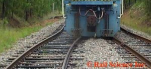
The root cause of these different wheel actions may vary widely and may be due to mechanical conditions, track conditions or human factors. Figure 1 shows the result of a typical split switch derailment.
Trailing Point Moves
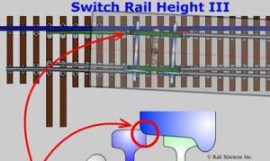
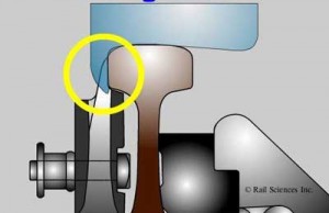
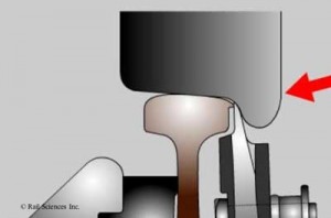
Let’s first deal with trailing moves through the point area. Engineering practice dictates that the point rail is maintained roughly 1/4-inch higher than the stock rail along its length and at the convergence between the point and the stock rail. This feature allows the wheel tread to be gently lowered from the top of the point rail onto the top surface of the stock rail as the point and the gauge face of the stock rail converge. If the point rail is lower than the stock rail, the outside edge of the wheel rim can engage the gauge corner of the stock rail, forcing the gauge open by rolling the stock rail outward, allowing the wheel to drop in (see Figure 2). This possibility is exacerbated if the wheel tread is moderately or extremely hollow worn with the development of a “false flange” on the outside edge of the tread. As of 2005, the AAR set a hollow wear limit for wheel treads of 4 mm.
A point rail can wear down over time and become lower than the stock rail. Or, a stock rail might be changed out and the point rail left in service. In this situation, the point rail will be lower than the new stock rail. A good practice is to change the point rail whenever the stock rail is replaced. Also, Section 213.135(c) of the Track Safety Standards states
“Each switch shall be maintained so that the outer edge of the wheel tread cannot contact the gage side of the stock rail.”
Facing Point Moves
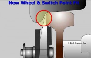
Most switch point derailments occur during facing point moves. If the point is new, the stock rail properly profiled, and the wheel tread relatively new, it is difficult to envision how a derailment ever occurs at the switch point because the wheel and the point have virtually no opportunity to interact. (See Figure 3 for an illustration of a new wheel operating on a new point.) But as we all know, in the real world, wear occurs on the wheels, points and stock rails. After wear sets in, it is easier to see how a split switch or switch point climb occurs. (See figure 4 for a view of a worn wheel on a nominal switch point.)
If a wheel flange splits a switch point, the switch point should be inspected to see if it is gapped due to improper geometry. This can be caused by a number of conditions, such as:
- The switch is out of adjustment.
- A condemnable thin flange wheel with heavy metal flow on the tip of the flange.
- The stock rail is worn lower than the point, exposing a gap.
- Heavy metal flow on the gauge corner of the stock rail is gapping the point.
- The switch has been run through and the switch machine damaged.
- There is lost motion in the switch machine due to wear.
- The stock rail is dynamically moving outward from the point due to inadequate bracing.
- The point rail is dynamically gapping due to pumping at the heel block that “see-saws” the point upward.
- A foreign object like snow, ice, rocks, piece of freight car, etc. lodges between the point and the stock rail.
- The point is chipped or broken, exposing a gap between the stock rail.
- Poor headblock ties or ballast support under the point allows the point to twist away from the stock rail.
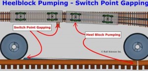
A common cause of switch point gapping is pumping in the heel block area. If the heel block is moving vertically due to loose bolts, poor tie condition, or mud in the ballast, it can dynamically allow the point to rise up in the air in a seesaw fashion. As the wheels of a preceding car negotiate over the heel block, the wheels of a trailing car may be approaching the point. Depending on the length of the couplers, the car lengths, and the coupler overhang, the timing may be such that the trailing wheels hit the gapped point. (See figure 5. for an illustration of how this action might occur.)
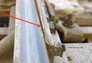
Figure 6 shows a switch point gapped up in the air due to heel block pumping. The only way to spot this condition is to watch the point dynamically as cars pass over it, or carefully inspect for weak conditions in the heel block area. The root cause may not be the point, but rather a condition 16 feet, 6 inches from the point at the heel block.
Thin flange wheels are a common cause of picked switch points. A condemnable thin flange wheel may also exhibit heavy metal flow on the tip of the flange that presents a sharp knife edge to a slightly gapped switch point.
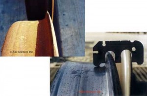
Figure 7 shows a condemnable thin flange wheel as verified with an AAR wheel gauge. Wheels that are worn to thin flange also are likely tread hollow, which means they may not be steering correctly, and may be crowding the gauge corner of the stock rail upon approach to the point area. A common situation is that a severely worn wheel is gauged, but in the words of the mechanical department “it won’t take the gauge.” Thus, the wheel is AAR compliant, but still shows signs of heavy flange wear and picked the point.
Alternately, you might notice that the opposite wheel on the same axle does not appear worn. This condition is called asymmetrical or uneven wheel wear. A good investigator will look beyond this condition for truck performance issues that might be causing the asymmetrical wear. Upon a detailed inspection, he might find tight side bearings, fouling between the centerbowl rim and the body centerplate, mismatched side frames, fastener contact around the bowl rim, worn or uneven centerplate conditions, or other reasons causing a stiff truck in either a right or left hand curve. The bottom line is that the root cause of the non-steering truck is not wheel flange wear, but rather an AAR condemnable condition elsewhere on the truck. That’s why it is important to inspect the entire car as a system, not just focus on wheel wear.
Another common cause of gapped switches is heavy metal flow on the lip of the stock rail gauge corner. This flow can either gap the point, or hold it off the gauge side of the stock rail, or alternately, the flow will cause the point to become chipped and broken. Grinding of switch stock rails is as important as grinding the mainline. Metal flow must be periodically removed in order to maximize the life of the point and prevent gapped points. Figure 8 illustrates how metal flow interferes with proper fitting of the points.
In Part 2 of this article, we’ll examine wheel climb derailments at switch points, and look at frog conditions that can lead to derailments.


