Effects of Wide Gauge on Derailment Potential (Part 2 of 2)
By Gary P. Wolf • January 1, 2005
Part 1 of “Effects of Wide Gauge on Derailment Potential” examined how wide gauge occurs, some of the symptoms and reasons why wide gauge is undesirable. Part 2 of this article explores how to correctly measure gauge and properly identify wide gauge as the cause of a derailment.
After a derailment, track gauge should be measured both before and after the point of derailment (POD). Most railroads specify that gauge should be measured for 15 stations (spaced 15.5 feet apart) preceding the POD, and at least 5 stations beyond the POD (if possible). The gauge is measured from a point 5/8 inches below the top running surface of the rail. In addition to measuring the static, or unloaded gauge, an attempt should be made to measure the dynamic, or loaded, gauge. The FRA specifies in section 213.13 of the Track Safety Standards:
When unloaded track is measured to determine compliance with this part, the amount of rail movement, if any, that occurs while the track is loaded must be added to the measurement of the unloaded track.
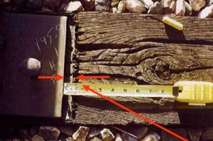
In practical terms, the FRA is saying that to correctly assess gauge conditions, any evidence of dynamic gauge widening should be added to the static, or unloaded, gauge. The telltale sign of dynamic gauge widening is evidence on the tie surface that the plate is moving laterally under load. This evidence is characterized by shiny wood fibers burnished by the action of the tie plate sliding laterally under each passing wheel. At the far extent of the plate movement, upturned wood fibers will be evident (see Figure 1). A gap between the base of the rail and the tie plate shoulders indicates that the rail is likely moving laterally against the shoulder of the tie plate.
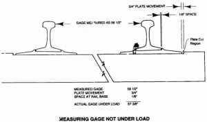
The approximate total dynamic gauge is determined by adding the amount of rail movement against the shoulder of the tie plate and the amount of tie plate movement on the surface of the tie. (Figure 2 indicates how these two areas of lateral movement are added to the static gauge measurement to approximate total gauge “under load.”)
Sometimes it’s not possible to get an accurate gauge measurement after a derailment because one or both rails have been rolled outward or the general pileup has compromised the integrity of the track structure.
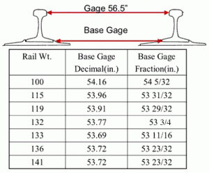
It may be possible in these instances, however, to measuring from the shoulder of one tie plate across to the shoulder of the other tie plate (if the ties are still present) to obtain the “base gauge.” Table 1 illustrates what the base gauge should be, based on the rail weight. For instance, the nominal base gauge when the gauge is correctly set at 56-1/2 inches is 53-23/32 inches for a 136-pound rail section. By knowing what the actual base gauge is, and what it should be, the approximate track gauge can be determined. This method is fairly accurate, but additional gauge allowances must be factored into the assessment if the rail gauge face is severely worn, or if negative rail cant is present. (Table 1 indicates the base gauge dimension for different rail weights.)
Symptoms of a Wide-Gauge Derailment
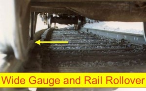
When you inspect the derailment scene, and one or both wheels of the first derailed car are down between the gauge of the track, you may have a “suspect” wide-gauge derailment. You may even be able to see a mark where the wheels dropped off the gauge corner of the rail. In other situations, you may find one rail rolled outward and wheel markings down the web of the rolled rail. Either of these scenarios is consistent with a loss of gauge restraint, and what is commonly called a “wide-gauge derailment.” (Figure 3 shows what a typical wide-gauge derailment looks like.
If the loaded gauge of the subject track leading up to the point of derailment has been correctly measured, and it exceeds the FRA standards, the use of the FRA T110 or T111 codes is appropriate. However, you may not have an exact violation of the FRA standards based on your gauge measurements. In this case, other issues should be assessed. The condition of the track, ties and fasteners leading up to the POD should be inspected for the following conditions:
- Spike killed ties.
- Missing or raised spikes.
- Evidence of dynamic gauge widening.
- Evidence of negative rail cant (or differential plate cutting).
- Evidence of heavy gauge-face wear on the rail.
- Severe plate cutting of the tie surface.
- Split or broken ties.
The presence of one, several, or most of these conditions at or near the POD, indicates a weakened track section that may fail under wheelset loading. In this case, even if the static gauge measurements don’t exceed the FRA standard, it is still appropriate to use the T110 or T111 cause code.
What if the track is in good shape, but wheels are between the rails? On occasion, it is evident that wheels have dropped within the gauge of the track, but the tie condition is good, the spiking pattern and condition are good, there is minimal plate cutting, and the quantitative measurement of gauge leading up to the point of derailment is within FRA standards. In this case, two possible derailment causes are:
- Stiff or Warped truck Condition.
- Human error during switching.
Stiff or Warped Truck Conditions
“Truck Warp: Causes and Cures” (Part 1 of 2) showed how warped trucks caused poor steering and excessive gauge spreading forces. Trucks warp, or parallelogram, for a variety of reasons. Conditions in the centerbowl or bolster can cause an increase in truck turning moment. These include:
- Interference at the centerbowl rim with the body centerplate.
- Fastener contact anywhere around the centerbowl rim.
- Incorrect repairs or rough centerplate surface.
- Insufficient, or tight, side bearing clearance (one or both sides).
- Excessive wear in the bowl or centerplate causing an egg-shaped condition.
- Incorrectly or overloaded car on one side.
Other factors can lead to poor truck steering. These include:
- Mismatched side frames (button mismatch).
- Mismatched wheel diameters (wheel tape sizes).
- Hollow worn wheels.
- Wedge rise or lack of damping.
If a detailed mechanical inspection of the first derailed vehicle reveals that one, several or many of these mechanical conditions are present, the primary cause of the “wide gauge” derailment may be of mechanical origin. In other words, the track structure was able to restrain normal gauge spreading forces, but not the excessive lateral forces that a particular car was generating. In a case like this, it is more appropriate to assign a mechanical code such as E46C: “Truck Bolster Stiff, Improper Swiveling.” It’s important to recognize that yard and industry tracks are built to standards designed to accommodate lower speed, and lower wheelset force environments. If excessive forces are placed on these tracks due to a poor mechanical curving condition, the appropriate cause code should begin with a “E” not a “T.”
Human Error during Switching
Spread gauge derailments also occur on good track with no obvious mechanical problem. In cases like these, human error may be the cause of a derailment. Poor train handling, even during switching, can cause excessive slack action, which leads to excessive drawbar forces. The forces imparted into the drawbars of freight cars are eventually transferred to the centerbowl, through the bolster, into the side frames, and eventually into the wheels. Thus, these drawbar forces are additives to all the other normal curving forces, and can overwhelm the track structure. When engineers use too much independent braking effort or excessive dynamic braking, excessive buff forces can be developed. Also, shoving against a heavy air brake reduction can likewise create heavy buff forces in the train. Simulations show that when buff forces exceed about 250 kips, the potential exists for compromising the gauge of nominal track. Bypassed couplers in switching operations can also exert tremendous lateral gauge-spreading pressure against the rails. Investigators should look for evidence of coupler impact or coupler shank contact against the side of the striker casting.
All of this is to say that the T110 “wide gauge” cause code should be assigned to a derailment in which the gauge measures in excess of FRA requirements. But before routinely assigning the T110 code, the role of human error and mechanical causes should also be examined.


