Inspection and Analysis of Switch Derailments (Part 2 of 2)
By Gary Wolf
Part 1 of this article examined trailing-point derailments, facing-point derailments and thin flange wheels. Part 2 examines wheel climb and frog-related derailments.
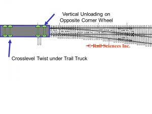
Crosslevel variances in turnout geometry represent a common cause of wheel-climb derailments. It’s not unusual to find bolted or insulated joints within 30 to 40 feet of switch points. This is particularly true in signaled territory where insulated joints are used. Like any set of bolted joints, mud pumping can occur at these joints. This pumping can cause a crosslevel twist or variance over the truck centers of the car, such that as the rear trucks are traversing the low joint, the opposite diagonal corner on the leading end of the car may be traversing the point rail in a reverse move into the turnout.
Depending on the amount of twist, some degree of vertical wheel unloading will occur on the lead truck. At the same time that the wheel is loosing vertical load, the lateral forces on the point rail may be reaching a peak value. The lateral forces developed on the point rail are substantial. The point rail, typically a section of straight rail planed to a fine tip, represents an abrupt change in direction, causing excessive wheelset angle of attack and attendant high flanging forces. Any reduction in vertical load at this point, coupled with a high lateral force, will result in a high L/V ratio with a high probability of wheel climb. Figure 1 shows a diagram of a potential track twist condition entering a turnout.
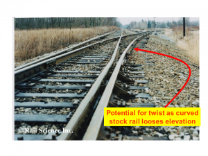
In a similar sense, the lead truck of a car may be positioned 40 to 50 feet beyond the point rail, and due to a crosslevel twist, the rear trucks may experience a similar loss of vertical load across the diagonal corner of the truck just as the wheels are traversing along the point rail. We often see this condition on industry sidings where the tracks slope off away from the main line down to an industry. Figure 2 shows an example of an industry lead track where the curved stock rail is clearly lower than the closure rail.
A mechanical condition that might contribute to wheel climb on the point rail is tight side bearings. A car with tight side bearings cannot accommodate even nominal track twist without causing significant loss of vertical load, especially across opposite diagonal corners of the car. Stiff trucks resulting from conditions such as fouling around the bowl rim, a twisted center sill, or a dry centerbowl, can also contribute to wheel climb.
Track geometry should be measured whenever a wheel climbs a point rail. The track geometry should be measured using 15.5-foot stations, accurately checking crosslevel variation at every station and every joint in the turnout, especially the heel block. Cars involved in wheel climb should be inspected to determine if any mechanical deficiencies are present, specifically insufficient side bearing clearance. In addition to checking crosslevel, the horizontal alignment deviation should also be checked using a 62-foot chord. Sharp changes in horizontal alignment, especially in the area of the closure rail, can contribute to excessive wheelset lateral force.
Chipped or Broken Switch Points
Many wheels climb switch points because the switch point itself is blunted or cracked from repeated wheel impacts. One of the more ambiguous clauses in the FRA Track Safety Standards is 213.135 (h) which states: Unusually chipped or worn switch points shall be repaired or replaced.
Exactly what constitutes an “unusual” condition, as referred to in this phrase, is the subject of great debate. The standard allows for some chipping of the point, but it does not allow an excessive amount of chipping. Where, then, do we draw the line? Some railroads have written internal standards that quantify the amount of chipping allowable on the tip of the switch point. As a rule of thumb, if the point is chipped at a depth of 3/4-inch or more, over a distance pf 12 inches from the tip of the point, you may be dealing with a defective point that could cause a flanging wheel to climb up and over the point.
Other railroads specify that the point must be repaired if it presents a blunt face that is more than 3/16 inches wide at all points closing along the straight stock rail. Thin flange wheels (but not condemnable) that flange hard against the stock rail are likely to find the chipped and broken switch point and create a climbing action.
To ensure a low risk of derailment, switch points exhibiting signs of chipping and breaking should be built up and ground smooth. Figure 3 shows examples of switch points exhibiting “unusual” wear, requiring repair.
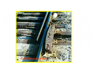
Switch point protectors (see Figure 4) are used by many railroads to prevent wheel flanges from striking the points. In order to be effective, they must be properly adjusted, as the face of the protector wears due to wheel rim contact.
Derailments in the Frog Area
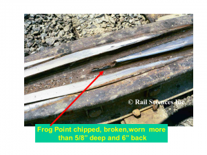
Wheels can “pick” frog points, just they can pick switch points. If the tip of the frog has become chipped and broken, a marginally steering wheel can be diverted from its intended path and proceed through the wrong side of the frog. The FRA Track Safety Standards are more specific when it comes to defining a chipped and broken frog point. Section 213.137 (b) states: If a frog point is chipped, broken, or worn more than 5/8 inches down and six inches back, operating speed over the frog shall not be more than 10 mph.
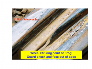
Frog points become chipped and broken (see Figure 5) when the guard rail is not properly adjusted with respect to the alignment of the frog.
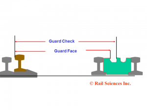
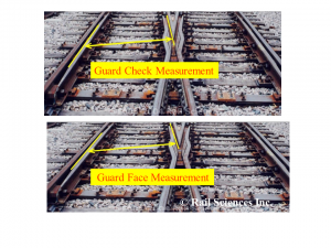
Section 213.143 of the FRA Track Safety Standards directly addresses the issue of guard rail placement vis a vis the location of the frog point. There are two important measurements that must be taken regarding the alignment of the guard rail and frog: Guard Check and Guard Face.
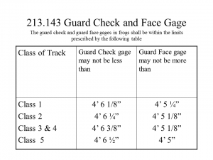
The Guard Check is a “not less than” measurement, and the Guard Face is a “may not be more than” measurement. Compliance with CFR213.143 is essential and there is little room for tolerance or slop in these measurements.
Figure 6 shows a diagram of these two measurements. Figure 7 shows the measurements overlaid on a turnout. Figure 8 shows the allowable measurements as contained in 213.143.
If the guard rail is worn, allowing a wheel to drift toward the frog point, the wheel will “crowd” the frog point, and possibly chip or break the point. Figure 9 shows a frog point exhibiting early signs of wear, where wheels are “crowding” the point. This is a telltale sign that adjustment of the frog or guard rail is required.
The Track safety standards also specify that a minimum clearance of 1-1/2 inches must be maintained in the guard rail flangeway opening. If the guard rail is too close to the stock rail, the wheel can become pinched, and cause a climbing action of the wheelset.
Railway Mechanical departments do a good job ensuring that all wheels are mounted on their axles with a back-to-back spacing of between 53 and 53-3/16 inches. These tight tolerances are closely checked and monitored. It is incumbent upon the track department to ensure that the wheelsets have the proper clearances when negotiating the frog area. Compliance with the track safety standards will ensure that the wheelsets stay on the “straight and narrow”.
There are other FRA rules and dimensions that should be checked following a derailment in a turnout. Railroaders are advised to become familiar with all the provisions of 213.133 thru 213.143. Many turnout derailments involve interaction of the car, wheels, turnout components, track geometry, speed and in-train forces. A systematic investigation of all phases of the operation is necessary anytime a turnout derailment occurs.


