Rail Cant Measurement of Concrete Crossties (Part 2 of 2)
By Arthur Clouse
Part 1 of this article examined the mechanisms that cause rail seat abrasion on concrete ties. Part 2 looks at existing standards for concrete ties and the systems that can be used to measure their performance.
The Federal Track Safety Standards prescribe minimum track geometry and track structure requirements for specific track conditions that exist in isolation. Railroads are expected to (and generally do) maintain “higher” safety standards. Railways may prescribe additional or more stringent requirements so long as they are consistent with sound maintenance practices. The FRA’s Class 1 – 5 standards are prescriptive performance requirements that address the unique characteristics of fastener reliability, concrete crossties and roadbed stability. The current federal standard’s limitations for gauge, alignment and track surface combinations may be too moderate, however, and may not prevent poor performance of concrete crosstie support conditions.
Currently, crossties are evaluated (inspected) individually by the “definitional and functional” criteria set forth in the regulations. Crosstie “effectiveness” is subjective, of course, and requires good judgment in the application and interpretation of the standard. The “soundness” of a crosstie is demonstrated when a 39-foot track segment maintains safe track geometry and structurally supports the imposed wheel loads with minimal deviation. Key to the track segment’s lateral, longitudinal and vertical support is a strong track modulus, which is sustained by a superstructure (rails, crossties, fasteners, etc.) and high-quality ballast characteristics that transmit both dynamic and thermal loads to the subgrade. Proper drainage is also required to provide the necessary structural support.
As the use of continuous welded rail (CWR) has increased, and elastic fastener technology and concrete pre-stressing techniques have improved, the use of concrete ties has become more widespread. Concrete ties now represent approximately 20% of the ties installed on the major U.S. railroads. Concrete crossties with polygonal construction have been shown to transmit wheel loads better than wood crossties, but they are susceptible to damage or degradation under high impact loads.
While changes in climate have little effect on concrete ties, wet climates and incipient or noncompliant geometry may cause high-concentrated, non-uniform dynamic loading, which is usually applied toward the field-side of the concrete rail base. Repeated wheel loadings rapidly accelerate rail seat deterioration over a track segment (usually in a pattern of five or more crossties) when the padding material fails and the rail steel comes into direct contact with the concrete. As problematic as rail seat abrasion is, it is difficult to measure and detect. Better, automated technology and manual detection procedures, along with the development of performance specifications for concrete ties, are needed.
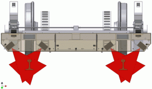
The industry has developed and currently uses a number of automated inspection technologies and rail profile measurement systems to monitor track conditions. The FRA’s Rail Profile Measurement System (RPMS) uses sensor heads containing a fan laser and camera-based imaging system (similar to most rail profile systems in use today) to record a complete cross-section of both rails. The RPMS is comprised of a total of four sensors heads that are able to capture the gauge and field sides of each rail (see Figure 1). The cameras in each head record the profile of the incident laser beam on the rail, and data processing electronics in each head reduce the camera image to a series of several hundred x – y data points representing the rail profile. The x – y data for each scan is transmitted to a host computer where it is converted to engineering units, using scale factors derived from factory calibration and in-situ alignment information. The nominal scale factors, combined with the higher resolution quality of the cameras, provide for a system accuracy of approximately 0.04 inches.
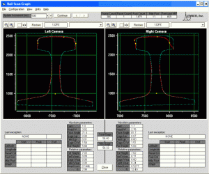
Rail profile data is typically collected at approximately 15-foot intervals, but the RPMS is capable of collecting, recording and analyzing rail profiles at 1-foot intervals at speeds up to 160 mph. The RPMS identifies the rail type (section) by comparing collected profiles with templates of standard rail profiles. Once the rail type is identified, the RPMS outputs a set of absolute parameters, which are determined from the measured profile, and relative parameters, calculated by comparing the measured profile and the reference template. The absolute parameters include rail cant, rail-head width, gauge-face angle, gauge side lip, field side lip, gauge-to-center width, and reference height. The reference parameters include total height, vertical wear, gauge wear, field wear, and rail head loss. Recorded profiles, reference templates and calculated values are all displayed and stored in real time by the rail profile software (see Figure 2).
Rail Cant Measurement
A concrete crosstie rail seat is described by the American Railway Engineering and Maintenance Association (AREMA) as a degree of slope (cant) designed toward the centerline of the crosstie. Accurate rail cant measurements can help identify potential problems at the rail / crosstie interface, such as rail seat abrasion, ineffective fasteners, plate cutting, missing or worn crosstie pads, and rail base / tie plate misalignment. Early identification of deterioration of the rail / crosstie interface is critical to preventing gauge widening and, in extreme cases, the potential for a rail rollover derailment.
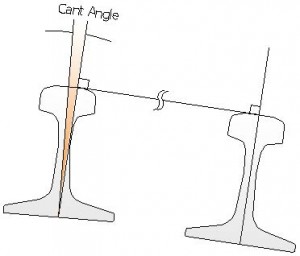
By itself, the RPMS cannot determine the amount of rail cant built into the rail / crosstie interface. The RPMS does, however, report cant in degrees as an angular variance from perpendicular to a line through the apex of both rails (see Figure 3). Since crossties are typically designed to cant the rail (1:40, or 1.4 degrees; 1:30, or 1.9 degrees, and 1:20, or 2.8 degrees) in the inward direction, the thresholds for left and right inward and outward cant can be reviewed independently or combined to include the angular difference relative to both rails. Most concrete crosstie track on U. S. railroads is typically designed with a 1:40 ratio that cants the rail in the inward direction 1.4 degrees toward the centerline of the crosstie. The sign convention used by the RPMS conforms to the industry standard, i.e., the top of the rail rotating toward the gauge side represents positive (inward) cant, and rail rotating toward the field side represents negative (outward) cant. Figure 3 shows the current FRA definition of rail cant in which the left rail as viewed illustrates negative (outward) cant.
ATIP Rail Cant Exceptions
The RPMS onboard the FRA’s Automated Track Inspection Program (ATIP) geometry cars uses a laser- / camera-based imaging equipment to measure left and right rail profiles, and is capable of reporting exceptions (POS<>NEG) in locations where cant exceeds a user-defined threshold. Starting with the measured rail profile and reference templates, the RPMS determines several parameters including rail section, rail cant, rail headwear loss, and the amount of rail overflow (lip). The RPMS onboard the ATIP cars is fully integrated with the Track Geometry Measurement System, Ride Quality, and other onboard electronic measurement systems. Because of this, detected rail cant exceptions are tagged with GPS location information and are included in the Track Geometry Inspection Report and are consistent with other onboard measurements exception types.
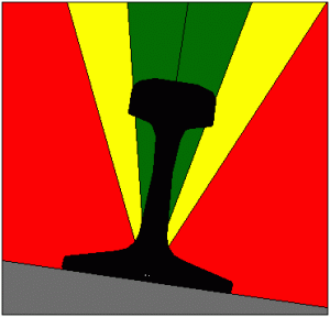
On the FRA geometry cars, there are two tiers of thresholds, referred to as “alerts” and “alarms,” which are used to identify “excessive” cant values. These levels are illustrated in Figure 4, where the yellow regions represent alerts and the red regions represent alarms. The thresholds are easily changed onboard the geometry car to adapt to crossties that orient the rail with different cants, i.e., 1:30 or 1:20 ratios. Table 1 shows the threshold values characteristically used during testing on the FRA ATIP cars and reported as advisories. Proper remedial action of the advisories identified through automated inspection relies on re-inspection in the field.
Ongoing Work
The Railroad Safety Advisory Committee, Track Safety Standards under task number 07-01 (concrete crosstie task force) has held several meetings since November 2007 to consider improvements relating to fastening rail to concrete crosstie. The work is ongoing with the following mission statement: The Task Force will consider all available scientific and empirical data or direct new studies to evaluate the concrete crosstie rail seat deterioration phenomenon and through consensus propose best practice, inspection criteria, or standards to assure concrete crosstie safety. The Task Force will develop definitions and terminology as required and disseminate pertinent information to detect through visual or mechanical inspection any safety concerns. The task force intends to issue a specific report recommendation to the committee in the near future.
Existing Regulatory Requirements
Crosstie regulations are contained in 49 CFR Part 213, Subpart D §213.109, which states in part:
Crosstie regulations are also contained in the High-Speed track safety standards under 49 CFR Part 213 Subpart G §213.335 (d) 1-7, which state in part:
|
Acknowledgements
Special thanks to Kevin Kesler, Susan Cook, Eric Sherrock, and Gary Martin of ENSCO, Inc., and to the men and women onboard the ATIP cars for their everyday contributions to rail safety. Further information about FRA automated track inspection technology is accessible at http://atip.fra.dot.gov/ or the FRA home page at http://www.fra.dot.gov/.
Arthur Clouse is Manager, Automated Track Inspection Program, Track and Structures Division, Federal Railroad Administration Office of Safety.
![]()


