Vehicle/Track Interaction from a Car Design Perspective
by Jeff Tuzik
Wheel/rail interaction doesn’t end at the wheel and rail. Sometimes it doesn’t even begin there. The lateral and vertical forces that affect the wheel/rail interface owe much to the design of cars and couplers — design choices that might seem ancillary to the subject, but are in fact critically important.
Consider the fundamental dynamics of a car moving through a curve. As the vehicle enters a spiral, the trucks have to pivot in order to follow the track, and the couplers have to be able to move laterally to accommodate the sometimes-significant relative motion of the cars preceding and following it.
While freight traffic occasionally has to navigate sharp curves in yards and sidings, most mainline curves are under 10 degrees (573 ft radius). As degree of curvature increases, so does the maximum swingout, which is the offset of the centerline of the car from the centerline of the track in a curve, Jonathan Sunde, Chief Engineer and Site Director at Strato, Inc., told attendees at Wheel Rail Seminars’ 2024 Heavy Haul conference. For example, a hypothetical car with a truck-center distance of 100 feet has a maximum swingout of 13.10 inches in a 5-degree curve, 26.23 inches in a 10-degree curve, and 79.93 inches in a theoretical 30-degree curve. Of course, most cars in operation have a truck-center distance of 31 to 65 ft, Sunde said. So practical swingout distances are much lower. A 65-foot car in a 10-degree curve has maximum swingout of 5.53 inches, or 2.52 inches for a 31-foot car, Sunde said.

AAR standards use a 13-degree curve to calculate maximum swingout for right-of-way clearance. This measurement informs AAR MSRP C S-2056 clearance plates (see figure 1). For standard car design, Plate B is the most significant, as it defines the car clearance envelope for unrestricted interchange access. “But clearance isn’t just about how wide or tall a car is, but how long, too,” Sunde said. Figure 2 shows how a hypothetical car with no clearance problems in tangent track could cause clearance problems in curves by virtue of its length.

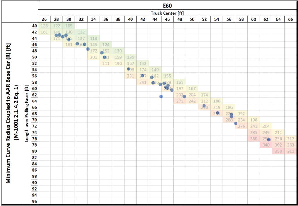
Coupler design is another factor that affects vehicle curve dynamics. Beyond plate clearance, which determines which tracks a vehicle is allowed on, vehicles must be able to couple to cars of varying lengths. “The coupler should ideally be in-line with the centerline of the track in a curve,” Sunde said. As car lengths increase, shorter couplers have more difficulty staying on the curve centerline; so longer cars tend to have longer couplers, as well. The numerous combinations of car type, coupler type, and degree of curvature can be distilled into a more digestible form as in the AAR M-1001 2.1.4.2 Eq. 1 Minimum Curve Radius Coupled to AAR Base Car diagram (see figure 3). In this case, the chart shows acceptable car lengths (truck center) for the E60 coupler. The green to red gradient indicates how close to the allowable limit each combination is; the blue dots represent actual car/coupler designs currently in operation (the one dot that falls outside the colored band is an error in the data, Sunde said).
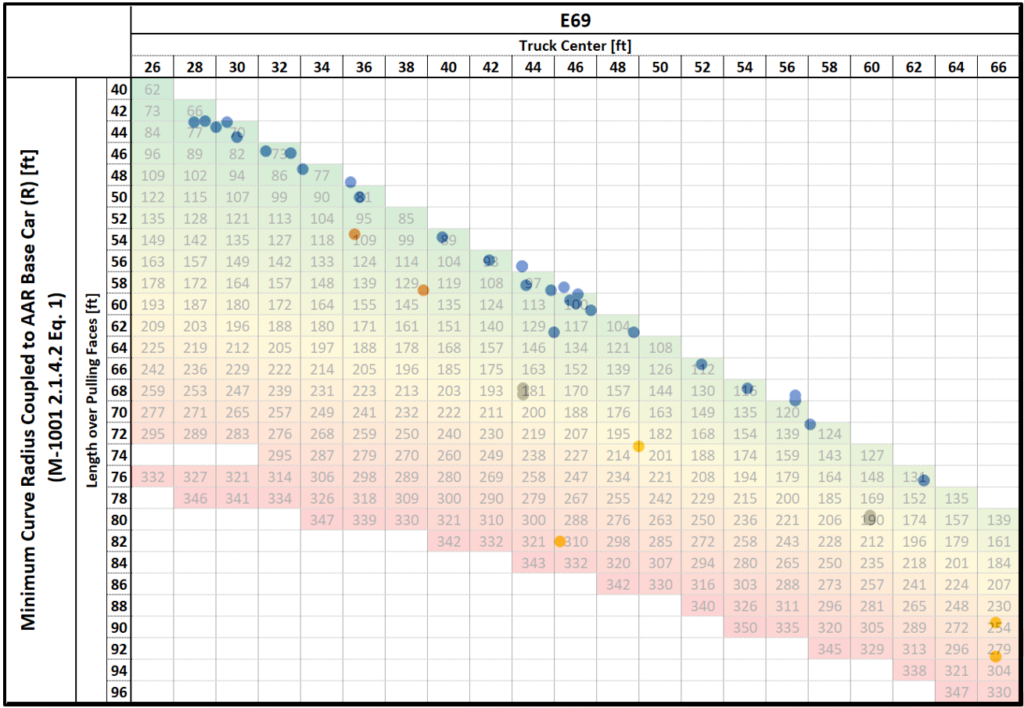
Figure 4 shows the same chart but includes longer couplers (E60, E67, E68, and E69) and illustrates the way longer couplers expand the acceptable range of car length/coupler type combinations. “Considering the whole range of designs, there are many cases where technically you could use an E60, but you’d be right on the edge of the limit. But if you’re within the limit, why choose one coupler over another?” Sunde asked. One consideration is the lateral swing of the coupler; some designs can travel further before contacting the bell-mouth shoulder (the opening through which the coupler shank emerges) and, thus, better remain in the track centerline. Another, more significant, consideration is that long, light cars (such as auto racks, for example) often have end-of-car cushioning systems (EOCCs) to protect the lading, and such systems typically necessitate a longer shank coupler, he said.
Curve navigation and vehicle length play critical roles in coupler design choice, but they’re not the only factors. Long shank couplers and those with more lateral swing are more at risk of no-couple events in which a slight misalignment of 2 to 4 inches, depending on direction, causes the knuckles or guard arms to impact and bounce off each other (see figure 5). A greater misalignment can cause the couplers to completely bypass each other and impact the car body. “These kinds of impacts can do significant damage and disrupt yard operations, so it’s something for car designers to keep in mind,” Sunde said.
Couplers also mediate buff and draft forces in decelerating and accelerating train consists. Even a minor brake application can cause the coupler shanks to impact the bell-mouth shoulder with significant force. This force is also transmitted to the wheel and rail and can impart high lateral forces at the wheel/rail interface. In severe cases, these lateral forces can cause wheel climb and gage-spreading.
The video at right (video 1) details a buff failure that resulted in lateral forces high enough to cause gage rupture. The train consist was made up of 68 loaded auto racks and double stacks, 42 of which were equipped with EOCCs. The graph at the top shows train location and elevation, the middle chart shows coupler force in kips, and the lower chart shows coupler deflection in inches. As the train descends the grade, the trailing cars run in, taking up all the slack and generating tremendous compressive force; with nowhere else to go, much of this force is transmitted laterally at the wheel/rail interface, causing the gauge to open enough to cause a derailment, Sunde said.
Draft forces such as those caused by acceleration can cause couplers and their respective end-of-car cushioning devices that were previously compressed (under buff force) to snap back to their maximum length. This can lead to excess lateral forces if it occurs in a curve and if severe enough cause a stringlining derailment. Excess draft force acting on coupler slack can also break the coupler entirely. A train consist with many cars equipped with long couplers and EOCCs can have hundreds of feet of slack at play when moving from a compressed (buff) to uncompressed (draft) state.

The video at right (video 2) shows how these types of high-slack draft failures unfold. In this case, a 103-car coil steel train with 100 EOCC-equipped cars experiences a draft failure as it begins to ascend a grade after descending another. The top chart shows the consist location and elevation, the middle chart shows buff and draft forces at the coupler (in kips), and the lower chart shows coupler deflection (in inches). “As the slack runs out, the force is transmitted to cars at the rear of the train like cracking a whip,” Sunde said. This event resulted in a broken knuckle. “In this case, the knuckle was a sacrificial member that protected the other components on the train. But if this happened in a curve, the results could have been much worse.”
To minimize the risk of these kinds of buff and draft failures, the AAR MSRP has a design standard relating to the length of couplers on long cars. This defines a maximum lateral/vertical force of 0.82 for a car on a 10-degree curve under 200,000 pounds of buff and draft force. Figure 6 shows multiple examples of car types currently in operation and how they perform under the AAR standard. “This gives you an idea of the theoretical limits these cars could endure,” Sunde said.
The effects of factors like truck center distance and coupler type on forces that ultimately manifest at the wheel/rail interface shows the importance of making carefully-considered and thoroughly-tested car design decisions. Cars that operate in the North American freight environment encounter a wide range of conditions and these AAR standards provide a framework for them to do so optimally.

Jeff Tuzik is Managing Editor of Interface Journal.
This article is based on a presentation made at the Wheel Rail Interaction 2024 Heavy Haul conference.


