Rail Grinding and Milling: How They Work, Where They Work
by Jeff Tuzik

Rail grinding is a well-established maintenance practice with multiple preventive and corrective applications. Rail milling is a more recent (introduced roughly 25 years ago) addition to the rail maintenance toolkit but although it’s use in North America has been limited thus far, it is widely used in Europe, Asian, and Australia, often in concert with rail grinding programs. While these technologies occupy a similar niche, they do not necessarily directly compete with each other, and in fact often complement each other. Both have strengths and limitations and understanding them is a necessary part of choosing the right tool for the job.
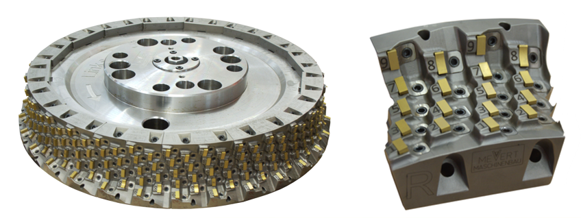
Fundamentally, rail grinding works by abrading the rail surface with the flat face of multiple cylindrical grindstones (see figure 1). The stones rotate on their axis (perpendicular to the rail) at high speed. Milling is a cutting process in which a cutter head with carbide milling inserts cuts the rail into the prescribed shape as defined by the shape of the carbide inserts (see figure 2). This is a peripheral milling process, meaning the cutter head rotates on its axis (and cuts) parallel to the rail surface.
Both grinding and milling can be used to achieve similar end-results: a running surface that is properly profiled and free of defects. “But the specific capabilities of each technology means that the details do differ,” Richard Stock, Global Head of Rail Solutions at Plasser & Theurer told those gathered at Wheel Rail Seminars’ 2024 Rail Transit conference. Differences in surface finish, production rates, logistics and overall maintenance strategy affect how and when these technologies are leveraged most effectively.
Target Profile
Rail grinders achieve their targeted profiles and metal removal by adjusting the angle and pressure of each grindstone or module. In this way, multiple stones can be positioned such that in aggregate, the entire transverse profile is defined (see figure 3). Larger grinders with more stones can thus cover more of the rail surface with more granularity or remove more metal in a single pass. Smaller grinders typically require multiple back-and-forth passes, adjusting the angles along the way, to achieve such coverage. The ability to adjust stone angles on the fly allows for “a very flexible transition between profiles and the ability to input any profile you want,” Stock said. The accuracy of rail grinders, in terms of achieving the target transverse rail profile, is typically 0.3mm or worse depending on operational conditions and required tolerances.
The process of milling instead defines the rail profile by the negative shape of the cutter head and carbide inserts. This means that each individual profile requires its own unique cutter head and inserts. Changing out the cutter head is a process that can be done in the field, but is a more involved process than the adjustments that are possible on a grinder. However, the purpose-built and static nature of the cutter heads also allows for very high profile accuracy in the range of 0.1 mm, and eliminates any potential human-error or variance in profile selection and adjustment, Stock said.
Surface Condition
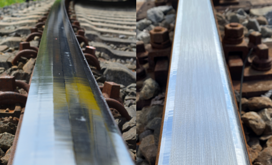
Rail grinding leaves behind a distinctive grind signature, which is in effect the pattern of “scratches” left by the rotating grindstones (see figure 4). The grind signature is affected by multiple factors: the grit of the grindstone, the power applied to the modules, and the speed of grinder itself. It is also affected by facets left on the rail, indicating traces of each individual grindstone. Typically, the grind signature is worn away from the running band in several days or weeks of traffic, depending on MGT, but the signature can cause problems as well, Stock said. A particularly aggressive grind signature can act as a starting point for various damage mechanisms like corrugation and rolling contact fatigue (and its associated defects).
Fortunately, best-practices and hard-won experience typically enable grinder operators to dial in the various parameters required to achieve a good surface finish. Some properties stipulate an additional step of acoustic grinding or “polishing” to ensure the surface does not contribute to damage or noise generation.
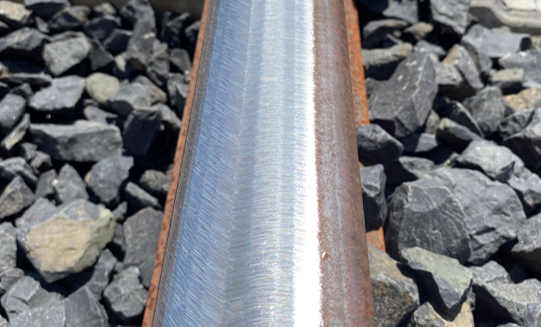
Rail milling, perhaps famously, leaves behind a near mirror finish (see figure 5). Immediately post-milling the rail surface is grooved in a pattern determined by the carbide inserts. These grooves can cause significant noise generation if not flattened and polished, Stock said. In most cases this post-processing is integrated into the milling machine itself. The longitudinal orientation of the polishing (and milling) processes leave behind a very low surface roughness, he said.
Productivity
The productivity of rail grinding and milling breaks down into several key metrics. The first is required metal removal; depending on initial profile shape and condition, metal removal can be localized or evenly distributed across the transverse profile in order to remove defects and/or achieve the target profile. This translates to the next metric: the number of required passes and average speed per pass based on the size and capability of the machine. And there are logistical and operational time constraints, such as the time required to change grindstones/cutter heads, and to transport the machine to and from the worksite, among others. These all determine productivity as a function of finished track feet per unit of time (such as per hour or per shift), Stock said.
There are fundamental differences in grinding and milling technologies that prevent a true 1:1 comparison of their productivity; but there are some metrics in which their functionality is sufficiently similar to warrant it. Rail grinding is a bi-directional process — that is, the machines are capable of grinding moving forward and in reverse and can apply different grind patterns on each pass completion. There is also great variability in grinder size from 8-stone grinders roughly the size of a rail transit car, to 700-foot-long 120-stone grinding trains. This variability applies to grind speed as well. While large production grinders can grind at up to 20 mph, the average speed per pass is in the 3 to 10 mph range, Stock said. Similarly, metal removal per pass can range from 0.1 mm to 1.0 mm.
Milling differs from grinding in that it is a unidirectional process; cutter heads only cut in one direction. Speed per pass averages between 0.2 mph to 1.2 mph, Stock said. From a productivity standpoint, these lower speeds are balanced by an average metal removal of 0.3 mm to 2 mm per pass — a figure much higher than similarly-sized grinding machines can achieve, he said. As in the case of rail grinding, these figures too, are dependent on the capability of the individual machine and the specific cutter heads and milling technology it uses.
Beyond Productivity
One of the main differences between the grinding and milling processes is related to the byproducts of their function. Rail grinding produces a great deal of heat, sparks, and dust. Nearly all grinders are equipped with dust filtration and collection systems, but such systems only lessen rather than eliminate the dust. The spark streams that grinders emit (from both sides of the vehicle) have to be actively mitigated as they can and do start fires in dry conditions. For the reason of preventive (and reactive) firefighting, grinders are equipped with spark shielding and with high-pressure hoses and large water tanks. Aside from sparks, much of the waste heat generated during rail grinding is absorbed by the rail itself, Stock said. This can lead to material transformation such as the formation of white etching layers (WELs) on the rail surface which may in turn initiate ancillary defect development; “The significance of WELs produced by grinding is an area of active research, and we know that grinding isn’t the only source of WELs,” he said.
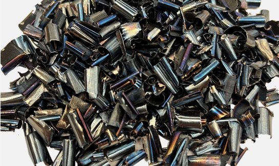
Rail milling by contrast produces no sparks or dust. Waste heat is primarily absorbed by the cutter head and metal chips cut from the rail; hence their characteristic blue hue (see figure 6). These chips are automatically collected by the milling machine and later recycled. The final polishing of the milled surface does produce a limited spark and dust stream that is typically captured by an onboard suction system. The relative “cleanliness” of the milling process can make it an appealing option for sensitive and/or confined areas, Stock said.
It should be clear that there is no dichotomy between grinding and milling. Both technologies are well-suited to freight and rail transit environments, and while there is undoubtedly some overlap in their function, there are also use-cases that favor one over the other. As rail milling becomes more visible in the North American market, it’s important that education comes along with it. Part of maintaining optimal rail condition is using the optimal tools to do it.

Jeff Tuzik is Managing Editor of Interface Journal.
This article is based on a presentation made at the Wheel Rail Interaction 2024 Rail Transit conference.
Unless otherwise noted, all images and figures courtesy of Richard Stock, Plasser & Theurer.


