
Switch Point Inspection & Wheel-Climb Derailment Prevention
by Brad Kerchof
This article originally appeared in the September 2025 issue of Railway Track and Structures. It is reprinted here at their courtesy.
Do you have experience arguing about derailment causes with another department? If so, chances are you have negotiated the cause of a switch-point wheel-climb derailment. The details of the conversation are predictable. The roadmaster to the mechanical supervisor: “Hundreds of cars have passed over this switch, and then that car derailed. It’s got to be a car problem!” The mechanical supervisor, if he’s on his game, responds, “What, are you nuts? That car has traversed hundreds of switches and then derails on that switch. It’s got to be the switch!”
More often than not, the argument comes to an uncomfortable conclusion when the mechanical supervisor pulls out their wheel gage. They measure the normal wheel parameters — flange thickness, flange height and tread wear, and pronounce the wheel fit for service. (None of these parameters have any effect on a wheel climbing a switch point. The one wheel measurement that is important in this instance—a vertical flange—is exceedingly rare. More about this later.) The roadmaster, unable to evaluate his switch point in a similarly quantitative manner, is forced to take the cause on switch out of adjustment or switch point worn or broken (FRA cause codes T311 or T314 if you are keeping score).
What does the FRA have to say about switch points?

Not much. FRA’s Track Safety Standards provide remarkably little guidance on what makes a switch point condemnable:
§213.135 Switches
(h) Unusually chipped or worn switch points shall be repaired or replaced. Metal flow shall be removed to insure proper closure.
The meaning of “unusually chipped or worn” is in the eye of the beholder and often depends on the inspector’s derailment experience. In fact, the best evaluators of switch point condition likely achieved that status following a very expensive education: years of switch-point wheel-climb derailments have refined their ability to identify high-risk points.
What three conditions are present in most switch point wheel climb derailments?
The first two are intuitive — a worn switch point and a worn wheel. The third condition is less obvious, but still important — wheel tracking position, or how close is the wheel flange to the switch point?
- A worn, broken or gaped point, such that the point provides a climbing surface for the wheel. A new (or like-new) switch point, properly adjusted, will not provide that climbing surface.

- A worn wheel — one with a worn flange root and often a sharp edge on the tip of the flange. A worn flange has two attributes that increase the risk of derailment. First, a worn flange root (the base of the flange) allows the flange tip to ride much closer to the top of the point, where it is more likely to get on top of a worn or broken surface. And second, the overflow at the tip of the flange, created by flange-to-gage face contact, can provide the grip needed for wheel climb. Figure 4 shows a worn wheel that presents a high risk of wheel-climb if it encounters a compromised point. The drawing in Figure 5 shows the profile of a worn wheel compared to the profile of a new wheel.
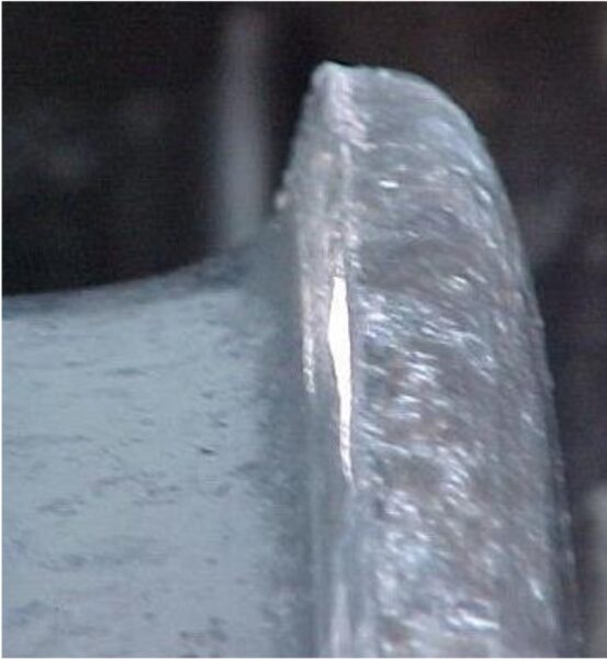
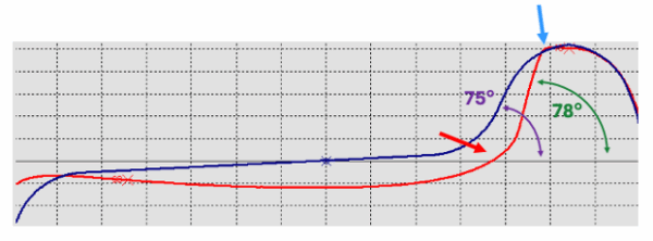
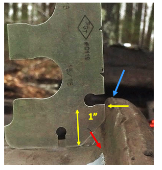
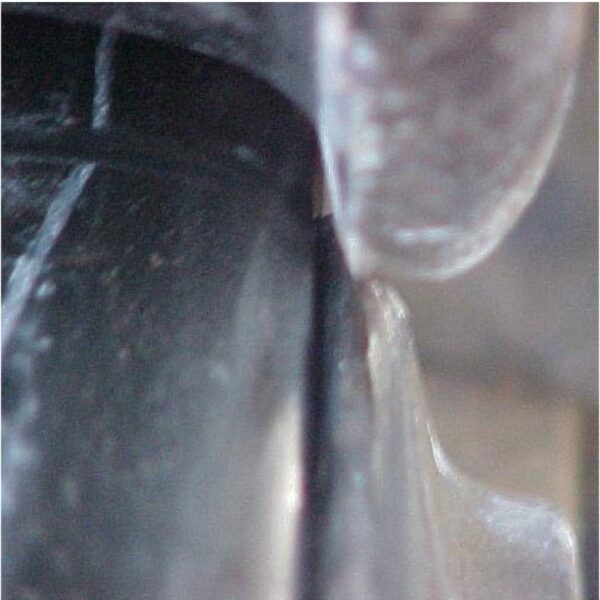
A word about vertical wheel flanges. While a flange may look vertical — see Figure 4 — the typical worn flange measures around 78o, matching the gage face angle of worn high rails. Figure 6 shows the challenge of condemning a wheel for a vertical flange. This wheel parameter absolutely has an impact on the risk of wheel climb. But encountering a wheel that fails the gauge is exceedingly rare — the gauge must contact the flange 1 inch above the tread.
- Tracking position — the worn wheel is shifted toward the worn switch point. You could have a ramped switch point and the ugliest wheel imaginable, but if that worn flange is not tracking against the switch point, wheel climb will not occur. Tracking position explains why some cars make it over a defective point and others do not (and why the first cars to traverse a run-through switch do not always derail).
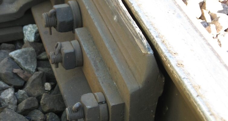
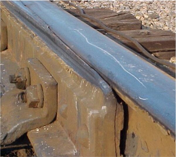
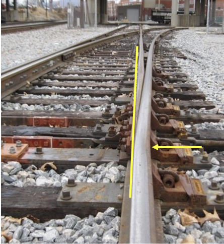
Did a wheel climb this switch point?
The switch point shown in Figure 8 had seen a lot of wheels pass successfully. And that fact is what caused the track inspector to say “good to go” on his last inspection. But a combination of stock rail wear and a slight gap exposed the tip of the point. And when the right wheel came along — one with a worn flange and overflow on the tip — that was tracking hard against the stock rail, the result was wheel climb.
Diverging points vs. straight points
It is no surprise that diverging points experience more wear than straight points (and why diverging points in yards get switch point protectors). The reason is related to tracking position: wheels rolling through the straight side of a switch are centered between the rails and normally don’t make flange contact. A diverging point, on the other hand, juts out from its stock rail into the path of the approaching flange.
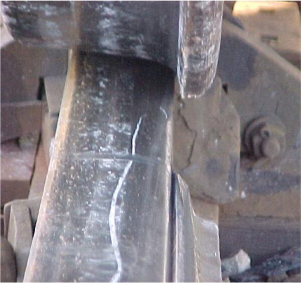
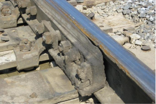
An indication that a problem is developing
Like so many other aspects of railroading, a switch point will usually tell you that a problem is developing. A point that shows flange contact is saying “pay attention to me as I wear.” A thin point is more likely to break out, especially if here is an overflow lip on the stock rail. Wheel contact can also cause a point to wear in the shape of a ramp (Figure 3). Both abnormal shapes can give a worn flange the purchase it needs to climb.
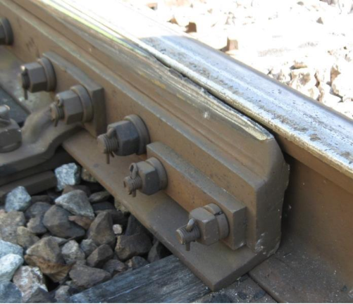
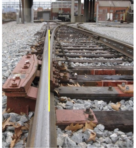
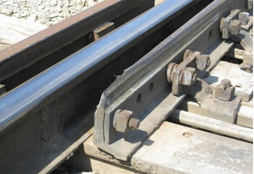
Any concerns with either of these switch points?
Figures 13 and 14 show the left and right points of the same switch. Both points have issues, but do those issues present an increased risk of derailment? Due to track geometry or in-train forces, wheels are tracking to the left, wearing against the left point and staying away from the right point.
Five switch point inspection tips
- Operate the switch both ways to observe how each point fits up against its stock rail.
- Look for wheel flange contact at the front of the point.
- Keep “tension” on your switch stand to hold the point tight against its stock rail.
- Grind stock rail overflow.
- Maintain your switch points with worn wheel flanges in mind!
If you inspect your switches properly (tips 1 & 2), maintain them properly (tips 3 & 4), and adopt the philosophy that you need to do a better job maintaining your switches than the car department does maintaining its wheels (tip 5), you should be able to avoid wheel-climb derailments.

Brad Kerchof is former Director Research & Tests, Norfolk Southern, retired.