WRI EU 2015, Part 2: Theory to Practice, Laboratory to Track
By Jeff Tuzik
A thorough understanding of the forces contributing to wheel/rail interaction requires a grasp of both theoretical concepts and operational practices. Speakers at the 2015 Wheel Rail Interaction Conference, European Union (WRI EU) addressed both, presenting findings from the lab and operating environment of vehicles and track.
One such area, equivalent conicity, the geometric relationship between a given wheel and rail profile, is at the core of wheel/rail interaction. But because of the difficulty of measuring it in real time (See WRI EU Part 1), it can be an esoteric and difficult-to-apply metric. “Many train managers don’t know what it is, let alone the values for the conditions in which they’re operating,” said Mark Burstow, Principal Vehicle Track Dynamics Engineer at Network Rail.
As a result, there is a clear industry-wide desire for a simpler, more usable method of equivalent conicity calculation, a so-called quick conicity method. “What we need is something that will give us something like 80% accuracy with 20% effort,” Burstow said. Current Technical Standards for Interoperability (TSI) only indicate maximum design conicity values (based on a number of wheel and rail profile templates) and provide little guidance on in-service conicity, he said. But with access to in-service equivalent conicity values, infrastructure managers could take a proactive approach to managing conicity.
The ability to measure equivalent conicity in real time benefits both wheel and rail asset management. “On many vehicles, they’re limited not by tread or flange wear, but by conicity (in terms of turning interval),” Burstow said.

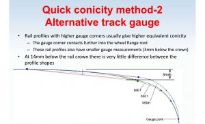
A quick conicity method underwent a number of validation studies as part of the DynoTRAIN project in 2014. The method is based on a single point measurement of track gauge at 3mm below the crown of the rail. While gauge measurements are typically taken at 14mm below the crown of the rail, there is often no significant change, or difference in rail profile at that point. But at 3mm, there is quite a big difference that is illustrative of variations in both rail profiles (see image at left). The 3mm measurement point formed the basis for a simplified calculation to determine conicity values. The study simply explored the relationship between gauge measurements at 3mm below the crown of rail, and actual “long-form” calculated conicity values. “We just wanted a simple indication of how good or bad conicity was at a given location,” Burstow said.
The results were promising. In every test case, the quick conicity method bore a strong relation to actual conicity values as determined by MiniProf measurement. “[The quick conicity method] gave us the location of a conicity issue, but little information regarding the culprit,” Burstow said.
The second phase of the study applied the same concept to wheel profile conicity. If a wheel profile has more material in the flange root area, it’s likely to contact the gauge corner of the rail, creating a larger rolling radius difference and thus higher conicity, Burstow said. As a result, the wheel quick conicity method was based on flange thickness as measured 3mm from the tread datum point.
Once again, the study compared wheel quick conicity values to actual conicity values. Once again, there was a strong correlation. “We found that wheels with a high quick conicity value will produce higher equivalent conicity when running over a given piece of track,” Burstow said. In other words, the method provided a simple and reliable way to measure or rank the general conicity values based on a single measurement.
Finally, the study compared the combined wheel and rail quick conicity values to the actual conicity values for specific wheels matched to specific rails. The findings showed that high quick-conicity wheels, matched to high quick-conicity rails produced high equivalent conicity.
The study showed that the wheel and rail quick conicity method is an indicator for general equivalent conicity values. “[The method] doesn’t tell you what conicity actually is, but it allows managers to get a sense of conicity with a single measurement,” Burstow said.
Quick conicity methods exemplify the difficulty of distilling complex systems based on complex calculations down to simple, actionable information. This is also illustrated by the complexities of rail life optimization and the concept of the magic wear rate.
Chasing the Magic Wear Rate
The trade-off between wear and fatigue is a well-known concept (See “the magic wear rate”). But techniques for managing rail wear and fatigue, in the pursuit of the magic wear rate continue to evolve.
The key to chasing the magic wear rate is regular, preventive grinding. The goal is to remove rolling contact fatigue (RCF) cracks in the early stages of their growth, before the growth rate becomes exponential. If cracks are allowed to reach the exponential phase of their growth, the amount of metal removal required to grind out the RCF results in dramatically shortened rail life. This leads to the seemingly counterintuitive fact that more frequent grinding results in less total metal removal, said Eric Magel, Principal Engineer, National Research Council, Canada — Surface Transportation.
Crack growth rate is also heavily dependent on the operating environment – factors like rail metallurgy, axle load, curvature, and operating speed. This means that the magic wear rate is an optimum value, but not an absolute; it has to be tuned to each individual system, he said.
One of the practical ways this is implemented is by following a cyclical grinding program that breaks the territory into segments of tangent track, mild, and sharp curves. Since the rates of crack growth differ in each segment, each segment requires a different grinding frequency. “The rates of crack growth on sharp curves are about double the growth rate on mild curves, and triple the rate on tangent,” Magel said.
Given these figures, an optimal single-pass grinding plan might target 1/3 of the tangent, 1/2 of the mild curves, and all of the sharp curves. The next pass grinds the next 1/3 of tangent, the second half of the mild curves, and all the sharp curves again. After six cycles of this grinding program, the grinding regime is effectively “reset.” A program like this allows the grinder to operate continuously at the same rate, while addressing the needs of the entire system, Magel said.
Dividing track into segments based on wear and fatigue rates is an important part of asset management in general, said Jay Jaiswal, Executive Director, AAR Rail Solutions. Because tangent and low-curvature track is subjected to different forces than sharp curves, they benefit from different maintenance and design strategies. Different rail materials for different track sections, etc. Rail is often replaced prematurely (before it reaches its wear limit) due to RCF and failure to chase the magic wear rate, he said.
System design can also play a role in chasing the magic wear rate. In North America, some railroads use composite brake shoes with embedded “scrubbers” to increase the wear rate on the wheel tread to remove incipient cracks. Wheel and rail metallurgy is also important in that many studies have shown that premium steels perform better in terms of both wear and RCF resistance: “I wouldn’t say it’s a universal cure to put in premium steels, but laboratory tests indicate that it’s generally a good way to go,” Magel said.
Noise & Corrugation
Rail grinding, of course, isn’t only used to manage RCF and chase the magic wear rate, it’s also one of the primary techniques used to manage noise generated at the wheel/rail interface. Since it operates in a very high-density region, the London Underground spends a lot of time and money addressing systemic noise. “Noise mitigation is one of the primary reasons LU grinds,” said Stuart Grassie, Principal, Rail Measurement Ltd/Stuart Grassie Engineering Ltd.
The wheel/rail interface generates significant ground- and airborne noise, but in the LU’s case, ground-borne noise is a primary target for mitigation efforts. Several studies performed by LU have shown that long-wavelength corrugations are responsible for the majority of ground-borne noise, Grassie said.
A well-executed grinding program typically results in a reduction of 10 to 20 dB at long (20mm to 1m) wavelengths, Grassie said. “However, it’s almost universal to see an increase in surface irregularities at wavelengths in the <20mm range after grinding,” he said. This is due to surface roughness, micron scale transverse cuts, so-called “grind signatures” introduced by the grinding stones. The effect can be particularly worrisome if the grind signature wavelength aligns with the wavelength of the existing corrugation: “You can end up with a worse problem than you started with,” he said.
Grinding out corrugations isn’t a permanent solution even in the best case scenario. They begin to develop again shortly after grinding. Any surface irregularities left (or introduced) by the grinder can rapidly accelerate the development, Grassie said. The criticality of surface finish in relation corrugation growth is one of the primary reasons even new rail is ground before going into service.
Surface irregularities of the type that can initiate long-wavelength corrugations can also be introduced to the system through weld restorations (such as those used to treat studs and squats), Grassie said. Like in rail grinding operations, it’s important to note that any poorly executed remedial action can cause more harm than good in the long run.
Truck Design
Many of the forces and damage mechanisms that cause problems like RCF, and corrugations can be addressed proactively – whether through preventive grinding, use of friction modifiers and optimized wheel/rail profiles, or other techniques. Truck design and selection, though one step removed from the contact mechanics of the wheel/rail interaction, can also play an important role in forces generated and transmitted to the interface.
In the UK, inboard bearings which are part of inside-frame bogies, are a common feature. This is due in part to UK track access fees; these bogies, such as the Flexx Eco Bogie, are generally lighter and thus less costly to operate, said Andrea Bracciali of the University of Florence.
Track access fees alone don’t determine bogie design. Like other parts of the wheel/rail interaction system, bogies must be selected or designed based on compatibility and optimization of the whole system.
A recent homologation test of a new high-speed vehicle provides a good example of this imperative. One phase of the testing put the vehicle through a 150-meter radius curve at very low speed. “During the test we observed a very strong stick-slip phenomenon,” Bracialli said. Stick-slip in this situation is the inevitable result of several factors: curvature, wheel conicity and rolling radius difference, and axle stiffness. Stick-slip like this is damaging to both wheel and track, and can initiate corrugations and other modes of rail damage. One of the ways wheel slip in curving is addressed is the use of top-of-rail friction management, which allows the wheel to slip without transmitting as much force into the track. But it’s possible that wheel slip could be mitigated by the design of the truck itself, Bracialli said.
“With the use of torque limiter or torsionally-flexible axle, we may be able to reduce longitudinal forces in curves,” he said. To explore the concept, Bracialli performed a series of running dynamics models and concluded that an axle with an integrated torque limiter set to 4000 newton meters could reduce maximum longitudinal forces by 60% in curves of varying radii. “The power that is dissipated at the torque limiter is a fraction of the power that would be dissipated at the wheel/rail interface,” he said.
Like other aspects of truck design, like curving performance vs high-speed stability, the use of a torque-limiter would present a difficult balancing act. If the torque-limiter intervenes too little, longitudinal forces are negligibly impacted. If the torque-limiter intervenes too much, it will wear rapidly and could become a point of failure. “You can slide at the wheel/rail interface or you can slide at the torque limiter. The energy has to go somewhere,” he said.
Regardless of the precise or practical application of the technology, the torque-limited axle design provides a novel approach to managing wheel/rail interaction forces away from the wheel/rail interface itself.
All the wheel/rail interface management techniques in use today began as theories. Many of these theories take decades to see practical application, and the railroad industry is often slow to adopt new practices. The time between the introduction of the magic wear rate, and industry-wide adoption of TOR friction modifiers and preventive grinding is a good example. But the rate seems to be improving. The WRI EU conference showed that complex, but theoretically sound best-practices are making their way to the field now more than ever.
Watch Interface Journal and Wheel-Rail-Seminars.com for information on WRI EU 2017, tentatively scheduled for September 2017.

All photos courtesy of Kordula Mittermayr.
Jeff Tuzik is Managing Editor of Interface Journal.


