Management of the Wheel/Rail Contact Interface in Heavy-Haul Operations (Part 2 of 2)
By Huimin Wu and Semih Kalay • January 2010
See Part 1 of this article here.
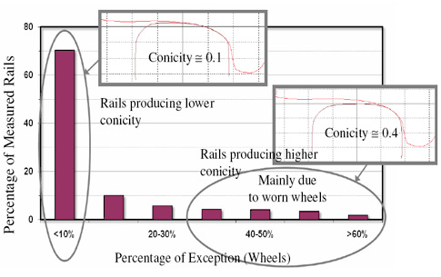
What are the differences between rail shapes that produce higher contact conicities and those that produce lower contact conicities? The profiles shown in Figures 1a and 1b illustrate the differences that can result in significant changes in conicity. The rail profiles that produced high conicity were selected from the rail group that produced more than 60% of the wheel exceptions shown in Figure 2 (See Part 1).
The rail profiles that produced low conicity were selected from the rail group that produced less than 10% of the wheel exceptions shown in Figure 2.
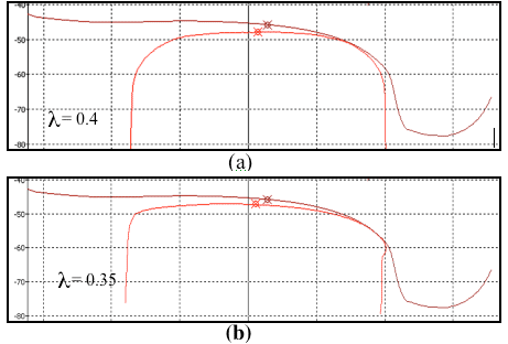
The differences between these two groups of rail profiles can clearly be seen. The rail profiles that produced low contact conicities have a relatively low rail shoulder compared to the rails producing higher contact conicities. Rails with considerable plastic flow at the gauge face of the rail (see Figure 1b) can also contribute to high contact conicity associated with reduced flange clearance.
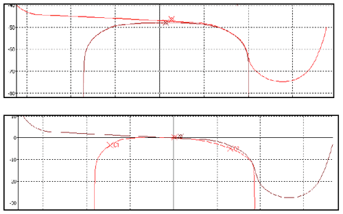
The contact conicity of worn wheels can be very dependent on the shape of the rail profile. Figures 3a and 3b show the high contact conicity that is produced by a representative worn wheel profile (selected from the group labeled >256,000 service km) contacting with two rail profiles. Both rail profiles have higher rail gauge shoulders. The rail profile shown in Figure 3b also has plastic flow at gauge face. The same worn wheel produces lower contact conicities when contacting rails with lower gauge shoulders (see Figure 4). New wheels tend to produce lower contact conicities when contacting both new and worn tangent rails (see Figure 5).
Note that the contact conditions shown in Figure 3 can also produce high contact stress due to a single, small contact area. When a vehicle experiences lateral oscillation, it not only transmits high forces into the truck structure, it also generates higher tangential force and creepages at the wheel/rail interface, which increases wear and the risk of rolling contact fatigue (RCF).
At certain locations, tight gauge also contributed to high contact conicities. The standard track gauge spacing of 1435 mm (56.5 inches) is measured at 15.6 mm (5/8 inches) from the top of the rail. Tight gauge conditions, combined with worn wheel profiles, can result in the rail gauge corner contacting a wheel at the flange throat. This is caused by small lateral wheelset shifts that are caused by track perturbations, vehicle dynamic movements, or a combination of both. This can result in higher conicity contact conditions and vehicle lateral instability. Tight gauge, which can be caused by improper installation, is exacerbated by metal plastic flow toward the gauge face of the rail, and/or rail movement.
A track geometry inspection identified a number of track sections with tight gauge conditions. Figure 6 illustrates the reverse correlation between the conicity exceptions and the variations in track gauge. The line of 30% of exceedance of wheels was the reporting criterion used in the inspection. Once above, it indicates that more than 30% of the wheels used in the assessment contacting the rail at that location exceeded the conicity threshold of 0.35.
Improving Vehicle Curving Performance
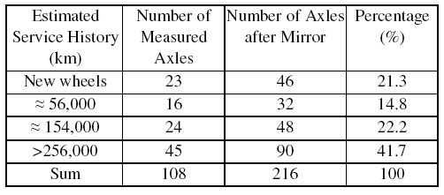
A track inspection was conducted on a 261-km, heavy-haul line, 25.6 km of which contained curves. All measured rail profiles were stored in three files named Sections 1, 2 and 3. The wheel profile database described in Table 1 was used in the curved track rail inspection.
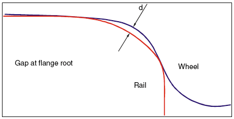
Contact conformity is a parameter used to evaluate bogie curving performance. The conformity of a wheel contacting the outer rail on a curve is a measure of the maximum gap between the wheel flange root and the rail gauge corner when the wheel is in flange contact with the rail, as shown in Figure 7. A large gap can lead to severe two-point contact, resulting in a larger rolling radius difference between the two contact points. This wheel/rail contact pattern can result in poor wheelset steering on curves and can generate high wheel/rail interaction forces, which increase wear and RCF on wheels and rails. Poor wheelset steering can also induce high gauge-spreading forces that can degrade the track.
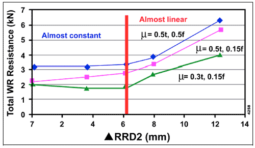
Figure 8 shows simulation results for a hopper with a 32.4-tonne axle load negotiating a 291-m radius curve, under three wheel/rail interface lubrication conditions. The total rolling resistance, also called wear index, is an indication of the energy consumed in the wheel/rail interface. (It is measured by the traction forces at the wheel/rail interface and the creepages).
ΔRRD2 in Figure 8 is the rolling radius difference between two contact points at the wheel tread and flange on the outer rail when curving. As ΔRRD2 is larger than 6 mm, the total rolling resistance increases almost linearly with ΔRRD2.
Table 2 lists the section length and the length of the curves (only counting the curves with a radius less than 873 meters). The smallest curve radius on this line is 291 meters. The threshold gap value (d in Figure 7) used to evaluate the contact conformity in this inspection was 0.5 mm.
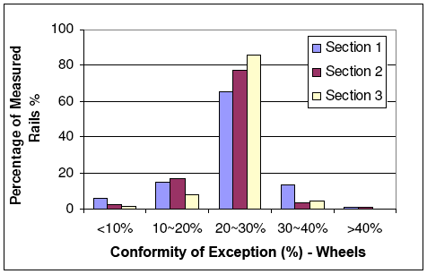
Figure 9 shows the distribution of contact conformity exceptions (i.e., where d> 0.5 mm) for the curves in this line with radii smaller than 873 meters. It shows that 20% to 30% of the wheels in the wheel database exceeded the contact conformity threshold when contacting 65%, 78% and 86%, respectively, of the rail profiles measured in curves of these three sections of track.
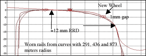
Of the wheels in the wheel database, 21.3% were new standard wheels; 14.8% had 56,000 km of service. Previous research has indicated that the current standard wheel profile can produce severe two-point contact when contacting the worn outer rail on curves. The rolling radius difference between the two contact points on the outer rail can be up to 12 mm (1).
Consequently, the poor conformity of wheel/rail contact, shown in Figure 9, was mainly caused by the new, or nearly new, wheels. Figure 10 shows the typical contact pattern produced by a standard wheel profile when contacting the worn high rail profiles in curves with radii of 291 m, 436 m and 873 m on this line. On the other hand, the worn wheels generally produce relatively conformal contact when contacting the worn outer rails on this route.
Wheel/Rail Profile and Track Gauge Maintenance
Based on the findings from the track inspection, recommendations related to the control of rail profiles, the control of track gauge, and the development of a new wheel profile have been made.
Rail grinding in tangent track sections is necessary, not only to remove surface defects such as corrugations and RCF, but also to reduce the propensity of vehicle lateral instability. The tangent rails tend to wear into a shape with a flat head. This shape moves the contact position from the rail crown region to the rail gauge region as the wheelset moves laterally. This can result in high contact conicity and cause plastic flow at the gauge corner.
Based on analysis of the rail inspection data, slightly lowering the tangent rail shoulder (to crown up the railhead) can improve vehicle lateral stability. With careful design, the grinding template for use on tangent track can ensure that crowning of the railhead is achieved. Correctly positioning the grinding templates should also be emphasized when grinding tangent track. Overcutting the rail gauge corner is not recommended, however, because it produces concentrated contact at the wheel tread, which can lead to hollow-worn wheels. The grinding interval also needs to be properly programmed. Rail grinding should be conducted before the tangent rails wear into shapes that can produce high contact conicities.
The track gauge in tangent track needs to be carefully controlled during the rail installation, especially on lines with concrete ties. Plastic metal flow on the gauge face of the rail can be prevented by reducing wheel contact at the rail gauge corner region through proper rail grinding.
Controlling Rail Profile on Curves
The outer rail on curves generally wears into a shape that produces conformal contact with worn wheels. Significant rail gauge corner cutting on the high rails of curves must be avoided during rail grinding in order to reduce the development of a severe two-point contact pattern for all passing wheels and also to reduce the “wear in” period for new wheels.
The wheel/rail contact pattern on curves may have no direct relationship to vehicle lateral instability. However, the contact pattern or the wheel wear pattern on curves may contribute to the formation of undesired worn wheel shapes that can produce high contact conicities. Significant rail gauge corner cutting on the outer rails of curves may not only degrade vehicle curving performance, but may also produce concentrated wear at the wheel tread and induce high contact conicity. Crowning of the inner railhead on curves is also recommended to reduce the risk of rail rollover and to maintain required rolling radius on curves.
Rail inspection further indicates the need to design a new wheel profile in order to improve the contact pattern of the new wheel / worn high rail in curves. The new wheel profile should correct the severe two-point contact pattern that is currently common when a new wheel contacts the worn outer rail of curves. Tests of a new wheel profile that were conducted in revenue service showed that the new wheel wore less and developed a better wear pattern than the current standard wheel.
The wheel/rail contact inspection technique that is presented in this article qualitatively assesses rail wear and the risk of RCF by assessing the influence of wheel/rail contact on vehicle performance and the wheel/rail interface. Analysis is based primarily on wheel/rail profile geometries and static wheel loads. Further development will include creepage and dynamic wheel/rail forces from a large population of cars with varying performance characteristics in order to quantitatively assess rail wear and the initiation of RCF.
This technique of managing wheel/rail contact will be implemented on track geometry inspection cars, ensuring that both track geometry and wheel/rail contact conditions will be inspected at regular intervals. With this, a more complete evaluation of track conditions can be used to determine the need and priority for rail maintenance.
References
1) Wu, H., Madrill, B., and Kalay, S., “New Wheel Profile Design and Preliminary Service Test Results,” Technology Digest, TD-06-023, Association of American Railroads, Transportation Technology Center, Inc., September 2006.


