
Norfolk Southern Embarks On a New Approach to Rail Defect Repair
by Jeff Tuzik
Some information in this article has been updated since the original publication date.
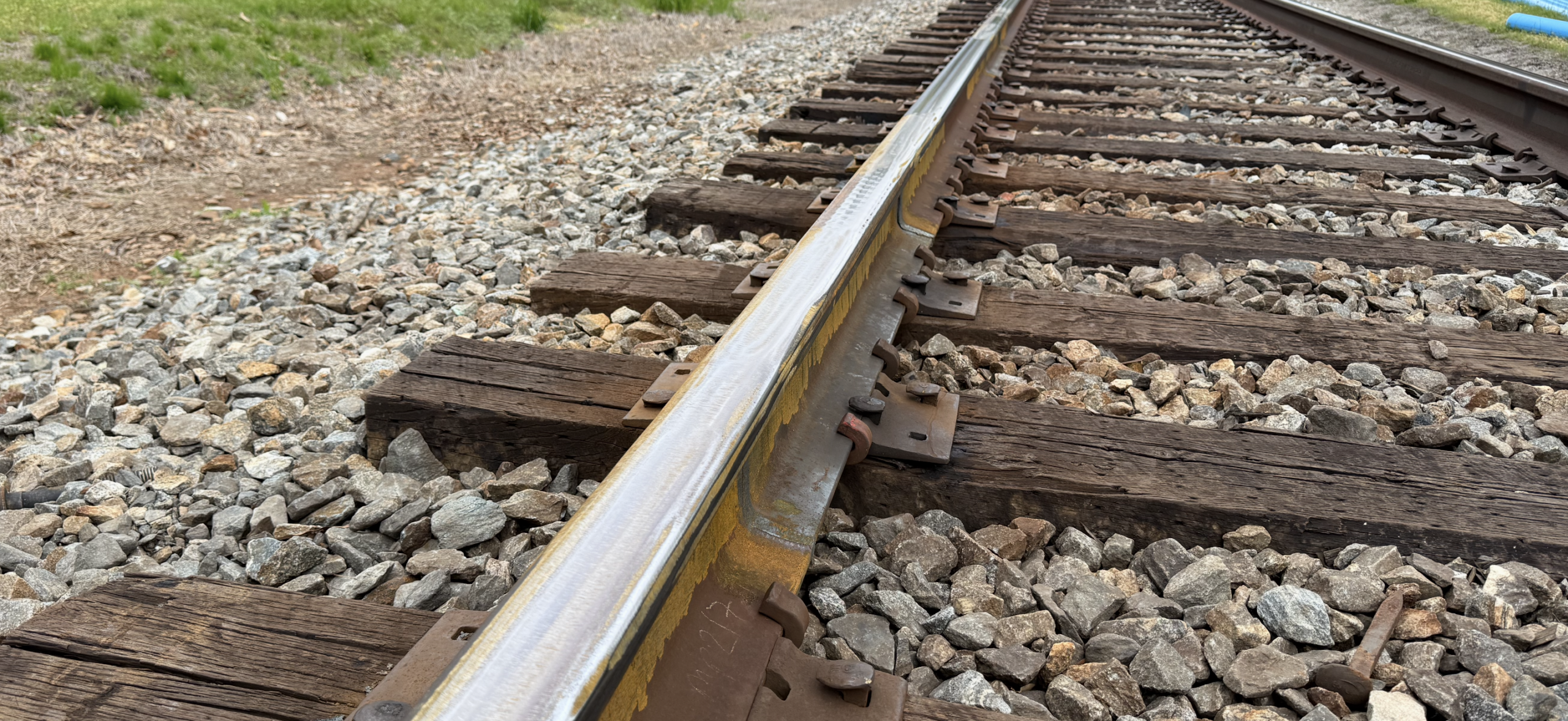
Internal rail flaws and defects are an unfortunate but unavoidable part of railroading. All railroads have them. All railroads have to repair them. Defect remediation, which involves cutting out the affected rail and replacing it with plug rail, is a necessary, but costly and time-consuming process; it’s a process with room for improvement. Norfolk Southern is currently rolling out a technology that aims to reduce the cost, track access time, and rail-mismatching drawbacks associated with the traditional defect repair process, and they’re already seeing results.
Norfolk Southern’s (NS) procedures for remediating internal rail defects are similar to any other class 1 railroad; due to FRA (Federal Railroad Administration) regulation and AREMA (American Railway and Maintenance-of-Way Association) standards, this is a somewhat standardized process. But it’s a complex process. “To repair a defect in continuously-welded rail requires multiple work groups, multiple track blocks, and, on average, 21 feet of tested, matching plug rail,” Christopher Lorren, Engineer – Rail Health Management at Norfolk Southern, told delegates at the 2025 Wheel/Rail Interaction Heavy Haul conference.
On NS, when a defect is detected, either via ultrasonic testing or visual inspection, typically a crew tailing the inspection vehicle immediately flags the defect location and installs joint bars if necessitated by the defect type and severity, as per FRA Track Safety Standards CFR 213. The location and severity of the defect also dictates the level of protection, such as a slow order, the defect is given. This process typically occupies a 0.5 hour to 1 hour block of track time, Lorren said.
The next step is for a section gang to unfasten the adjacent rail, cut out the defect and install the plug rail, temporarily, via joint bars, and refasten the track. This typically requires an hour to 1.5-hour block of track time, he said.
The final step is to perform the welds. NS uses both thermite and flash-butt welding on their system, depending on the defect location and availability and logistics of welding trucks and crews (although flash-butt welding is preferred). Regardless of the weld type, these crews are tasked with removing the joint bars and welding the plug rail in place to complete the defect remediation process. This block of track occupancy can range from 1.5 hours to 4.5 hours depending on the complexity of the job, the type of weld, and the availability of track blocks, Lorren said.

In 2024 alone, NS tested more than 100,000 track miles, detecting over 7,500 defects in mainlines and sidings, Lorren said. Remediating these defects required a total of:
- 157,000 feet of ultrasonically-tested, matching plug rail
- 60,000 bolt holes and bolts
- 30,000 joint bars
- 22,500 saw cuts
- 15,000 welds
That adds up to a lot of track time. “Our primary goals are to decrease our exposure and improve our efficiency,” Lorren said. “We want to be able to remediate a defect with a single crew, in a single block.”
Exposure and Efficiency
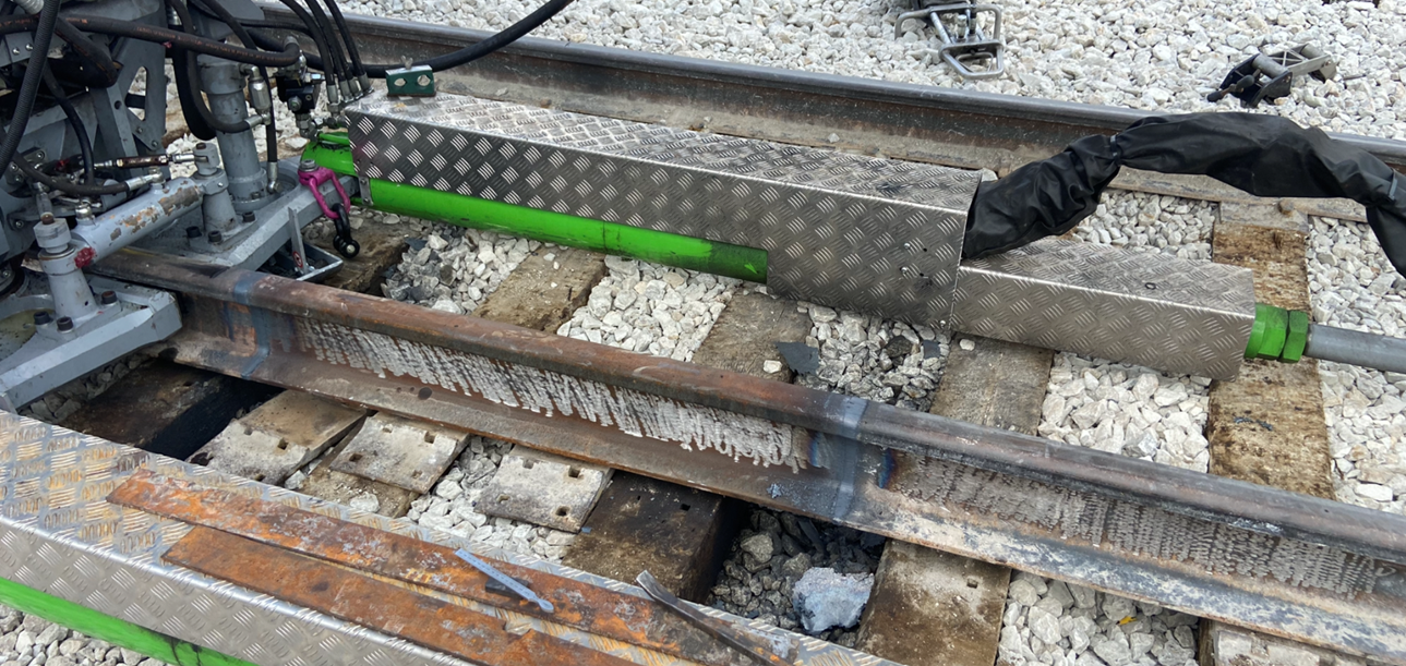
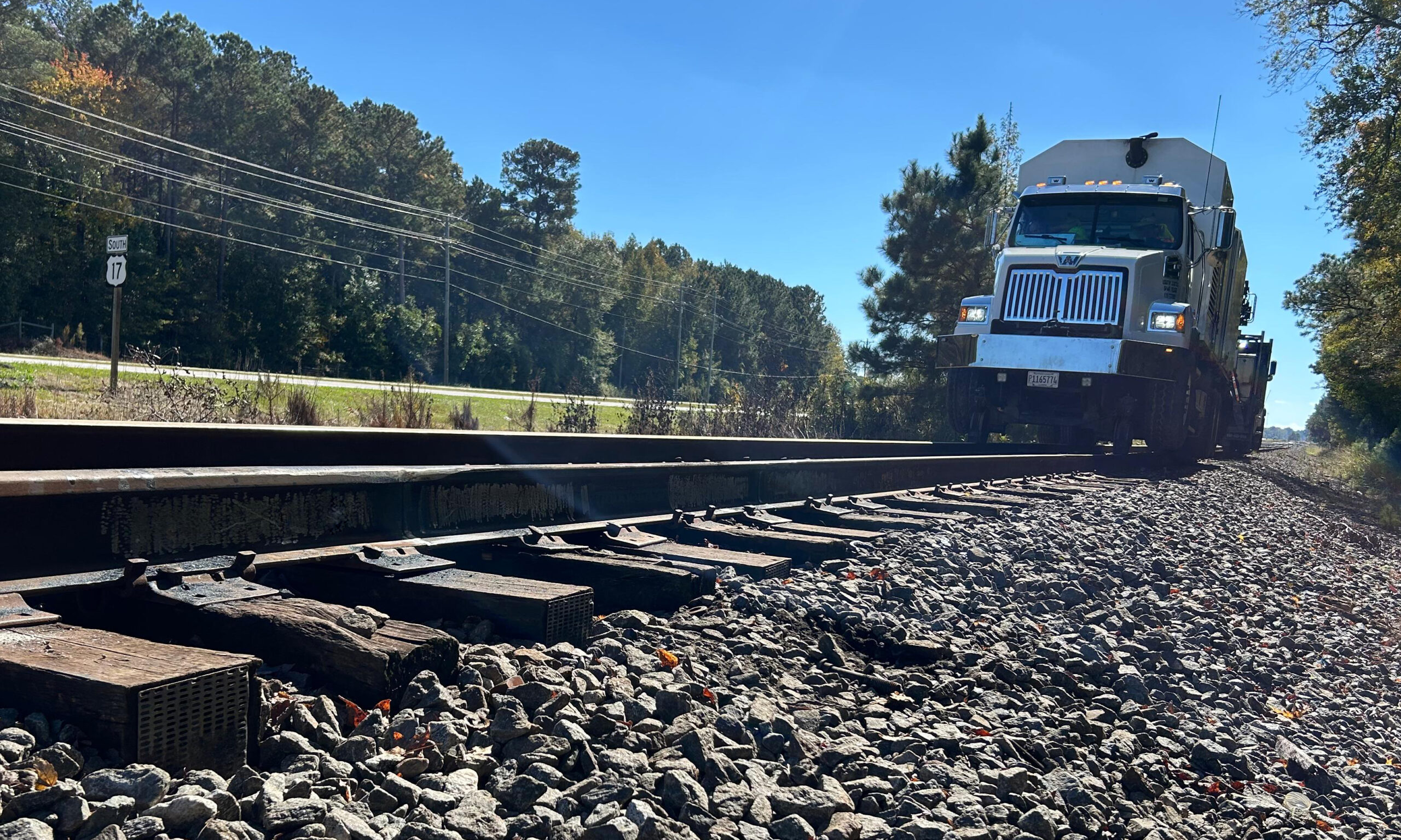
Of course, a single crew is capable of removing, replacing, and welding a piece of rail, but there are logistical and technological constraints to consider. The average length of plug rail NS uses, at ≈21 ft, means that most jobs necessitate the use of a specialized grapple vehicle to transport and maneuver the plug and defect rails. “You lose a lot of time simply setting on [track] and setting off when you’re using these bigger hi-rail trucks,” said Kristopher Koski, President of ONE Rail Group. “If you can eliminate the need for a piece of equipment like that, you’re already more efficient.” The only way to eliminate the need for a grapple truck or overhead crane is to use a smaller section of plug rail. This would also have the add-on effect of reducing the labor and time associated with rail handling and with unfastening and refastening the track during the repair process, he said.
Ensuring the quality and consistency of welds is critical to the process; a failed weld is bad for both efficiency and exposure. A failed weld precipitates more track time, more material, more cost.
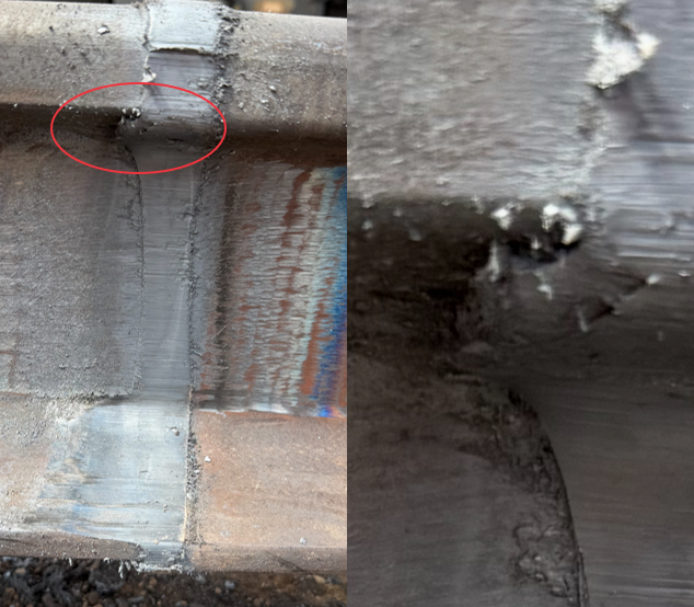
Thermite welds have a typical lifespan of ≈500 MGT, NS’ Lorren said. The most common mode of failure is “finning” at the base of the rail. Finning occurs when molten metals leaks out between the welding mold and the rail surface and fails to fully bond with the rail. This fin of material acts as a stress-riser and can initiate a fracture as the rail experiences bending and torsional stress over time. Figure 1 shows an example of a thermite weld failure due to finning at the base. “Thermite welding is a very manual process; it relies on a trained and skilled welder. It also relies on well-matched rail and plug rail,” he said.
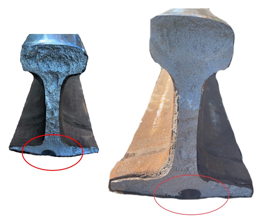
Electric flash-butt (EFB) welds are generally preferred to thermite welds. They typically have a lifespan of 1500 MGT, three times that of thermite welds, Koski said. “Flash-butt welding is the industry standard for long-term rail repair, but that doesn’t mean it can’t be improved.” Flash-butt welding removes much of the manual aspect from the equation by virtue of being a mechanized process, but these welds can fail, too. And when they do, the failure is often related to rail-mismatch, he said. In such cases, shear lip at the fillet radius between the rail head and web (see figure 2) acts as a stress riser and can initiate a fracture (see figure 3) under stress.
But matching plug rail to extant rail is not an easy task. “Railroads simply don’t store a lot of rail; those days are over,” Koski said. As a result, maintenance crews are rarely, if ever, able to find plug rail that perfectly matches the rail it’s replacing in terms of wear level and pattern.
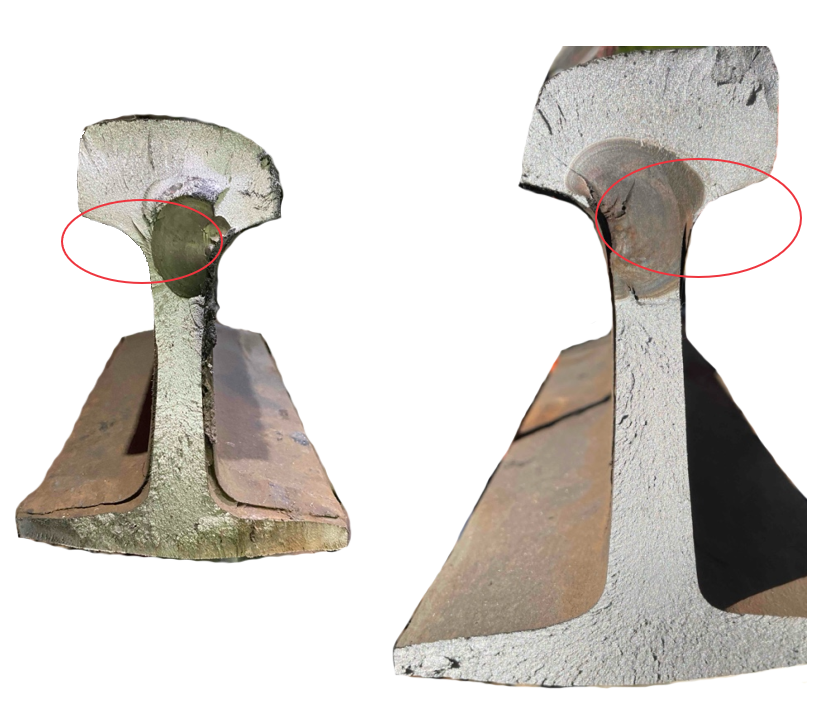
The current AREMA standards allow for ±5 mm of mismatch between the rail and plug rail—figure 2, for example, shows a 4.7 mm mismatch (3 mm in the base and 1.7 mm in the head). “This [allowable mismatch] became the standard because railroads wanted to be able to weld 136 lb rail to 132 lb or 141 lb rail without having to put in a transition rail,” Koski said. The mismatch allowance makes it easier to find and install an acceptable plug rail, but the potential consequences of mismatch such as the inadvertent creation of stress risers and eventual weld failure must also be considered.
Rail Inserts
With the aim of reducing track occupancy time, increasing operational efficiency, and improving overall weld quality and consistency, NS has recently begun to trial a new defect remediation procedure that, for individual defects, uses small, proprietary machined Rail Inserts™ in place of traditional plug rail.
The inserts, which are in effect, very short sections of purpose-built plug rail, measure only 5 ft in length. They are manufactured from new rail, ultrasonically tested, and milled to match the extant rail to within 1 to 2 mm of mismatch, Koski said. They are small enough that a grapple truck or overhead crane is not necessary to transport or handle them.
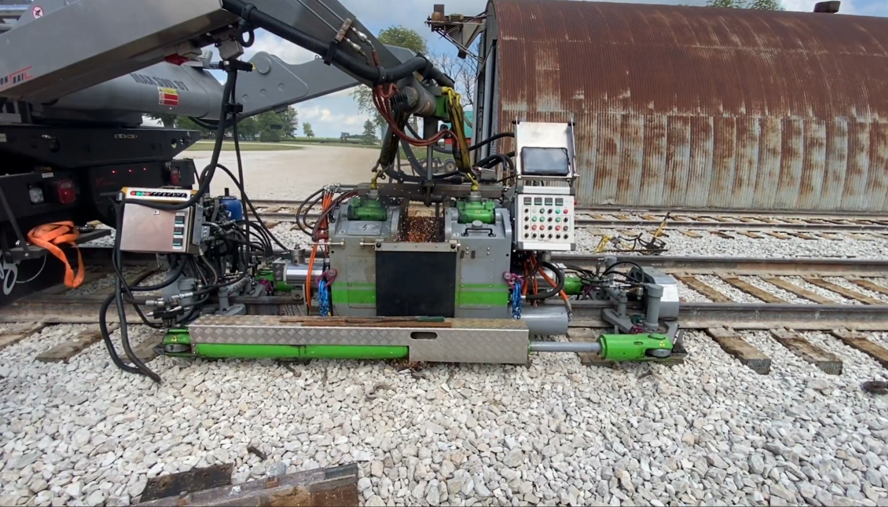
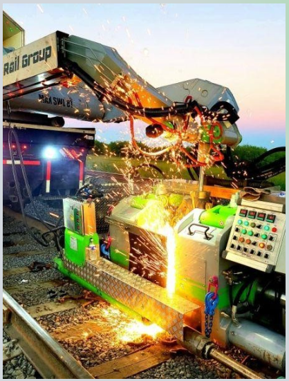
The 5-foot inserts are, in fact, too small to weld with standard flash-butt equipment, which typically requires at least ≈12 ft of rail to ensure proper geometry and crown at the weld point, Koski said. The use of 5-foot inserts requires a welding head designed specifically for the task (see figure 4). One of the benefits of the design, and of welding such small pieces of plug rail, is that both welds fit within the envelope of the rail puller. This means that both welds are performed under compression; the crew doesn’t have to wait for the first weld to cool before performing the closure weld because the insert is never in tension during the process, he said. This saves time that can add up over the course of multiple welds in a shift. The welding head is also able to perform standard flash-butt welds, so welding crews don’t have to skip over standard joint removal/repair jobs.
In addition to 5-foot inserts, however, One Rail Group has also developed a new 7-foot rail insert (a so-called Rail Insert 2.0 [see Figure 5]) that aims to solve two emergent issues: first, the 7-foot insert can replace and entire 5-foot insert and its associated welds, should the need arise (such as weld defect or rail/insert mismatch—although no such defects have been detected to date), and second, the 7-foot insert length means that the insert itself spans older 6-hole-joint seed rail, meaning that twelve bolt holes (6 on each side) can be removed quite efficiently and replaced with CWR rail.
Using these rail inserts, NS has, as of June 2025, repaired over 75 defects on their track. And they’ve done so in one step, using limited crews. Track occupancy time is down, too. A crew using the inserts can fully repair a defect in an hour and a half or less, NS’ Lorren said. “Conservatively, we’re saving one to two hours per defect when it comes to single-defect repair.” A five-person crew currently working with the inserts and the insert welding head now averages over 9 welds per shift—a figure that’s close to the output of a full flash-butt welding crew and significantly above that of equivalently-manned thermite crews, he said.
“We’re at the first step of the process. We’re still testing and proving things out,” Koski said. As the program continues, NS and One Rail Group plan to expand the program to additional crews—current plans call for 8 to 10 crews installing rail inserts on various Class 1 railroads by 2026. There are also plans to expand rail insert inventory tracking such that a maintenance crew can query a database based on rail type and head loss to find the proper insert for the repair.
As Koski said, these are early days for the program. The theory is sound and initial results are promising, but there isn’t much data to analyze yet. That will change in the coming months and years as these inserts accrue tonnage and the process is refined. But railroads are already taking notice; CSX has recently begun to trial this technology as well, and One Rail Group is developing a stockpile of inserts to meet demand for 2026—as of November 2025, they’ve used rail inserts to repair over 250 defects on class 1 railroads. It’s always interesting to find that in an area like defect repair that seems to be a “solved problem,” there is still room for innovation.

Jeff Tuzik is Managing Editor of Interface Journal
This article is based on a presentation made at the 2025 Wheel/Rail Interaction Heavy Haul conference.
All images are courtesy of Norfolk Southern and ONE Rail Group except where otherwise noted.