
Curve Superelevation: Problems and Solutions
By Gary Wolf • January, 2006
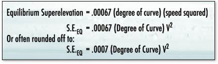
Railroad engineering managers have been struggling with the problem of how much elevation to place in a curve since the first steam engines started turning a wheel. While the physics and calculus of the matter seem straightforward, the application of those formulas is where problems arise. The classic formulas used by the Federal Railroad Administration (FRA) and others to determine correct superelevation contain two variables: the degree of curvature and the speed of the train.
Thus, the correct amount of superelevation to balance the train’s centrifugal forces is:
It looks like a simple matter of plugging in the numbers and calculating the answer. But it’s not a simple matter. While the degree of curvature is generally fixed, the correct speed to use causes much confusion. There are several recurring scenarios that can create problems.
Most difficult, perhaps, is dealing with the problems associated with heavy grade territory, where uphill trains may struggle to maintain the minimum continuous speed of 12 mph, while downhill trains can round the curves at the timetable speed of 35 mph. Which speed do you use in the formula?
A second recurring problem is accommodating both freight and passenger trains in the same corridor. The tonnage-laden freight might struggle to make 40 mph, while the sleek and horsepower-heavy Amtrak train can move along at 79 mph. Which speed do you use in the formula?
Curve speed restrictions and siding entrance/exit locations might create situations where trains can’t make timetable speed due to operating conditions. Which speed do you use in the formula? Determining the correct amount of “super” is not as easy as it seems at first blush. And in today’s world of 286,000-pound cars, and high-center-of-gravity cars, the consequences of improper elevations are severe.
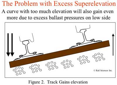
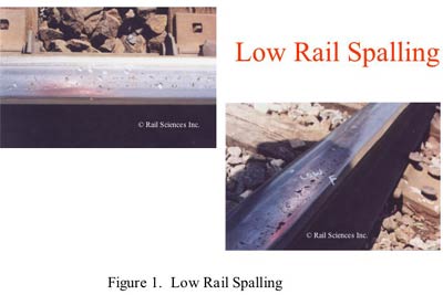
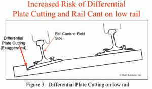
These consequences can range from low rail spalling, increased curve elevation, rail cant, and at its worse, an increased risk of derailment (see figures 1, 2, and 3). In the past several years, Rail Sciences has investigated numerous derailments where curve elevation was a significant, if not primary, factor in the derailment causation. One particular problem that we have noticed is the cascading of medium-tonnage secondary lines to short line operators. The original “Big” railroad might have operated the line as class 3, where the new shortline operator decides to downgrade to Class 2, or even Class 1 speeds. Thus, the shortline operator is saddled with numerous curves elevated for 40 mph when unit coal trains struggle down the track at 10 mph.
FRA definitions
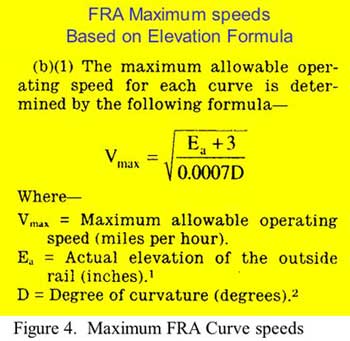
The FRA track safety standards (TSS) Section 213.57 defines maximum allowable curve speeds based on allowing up to a 3-inch unbalance (see Figure 4). Appendix A, of Section 213 provides charts defining maximum allowable speeds for various degrees of curvature and superelevation. While there are penalties for over-speed operation, there is no prohibition against operating a train at a speed lower than the timetable speed, despite the danger this presents.
Theory of Under Balance
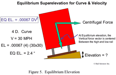
The Newtonian physics of calculating a suitable superelevation can be seen in Figure 5. A suitable elevation can be determined based on the centrifugal force developed at a given speed, the height of center of gravity of the equipment and the gauge of the track. Following the formula for a 4-degree curve and a timetable speed of 30 mph, assuming the use of equipment with average CG heights and nominal 56-1/2-inch gauge track, a roadmaster will presumably put 2.4 inches of elevation in the curve. During his inspection trips, he may start to notice the development of a series of undesirable conditions:
- The low rail starts spalling.
- Differential plate cutting causes the low rail to cant to the filed side.
- The curve starts to gain elevation over a year cycle.
If he checks his calculations, he’ll find that he did them correctly. So, what went wrong? The equations didn’t reflect the reality of the situation. The timetable speed was correctly listed as 30 mph, but few, if any, trains live up to this expectation. In the real world of railroad operations, speed is a variable, and many trains operate at less than the timetable speed for a variety of reasons:
- Locomotives fail to develop full horsepower.
- Slow orders placed on the track.
- Train running at restricted speed due to signal or warrant control.
- Train over tonnage.
- Trains running on approach signals.
- Sticking brakes.
- Inexperienced crews.
- Weather conditions.

So, while trains rarely exceed the timetable speed limit, there are numerous reasons that trains operate under the posted speed limits. To accommodate this reality, most railroads under-balance the curve at 1 – 2 inches below equilibrium elevation. In the case of the above example, a more appropriate elevation would be given as:
(2.4” Equilibrium Elevation) minus (1 inch under balance) = 1.4 inches
Armed with this information, the roadmaster can accurately re-elevate his curves and eliminate many of the problems associated with an imbalance in elevation, such as low rail spalling, differential plate cutting, and unwanted shifts in track elevation. By taking into account the reality of operating under the speed limit, it is possible to find an optimum elevation that accommodates the predominance of trains that pass through the curve.
Superelevation and Derailment Risk
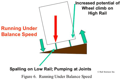
In addition to degradation of the track structure, excessive elevation in curves can increase the risk of derailment. When running significantly under balance speed, or operating on over-elevated curves, a significant portion of the vertical weight of the car is transferred to the low rail (see Figure 6).
This weight transfer to the low rail increases derailment risk for the following reasons:
- Greater vertical weight on the low rail increases spalling, the attendant growth of potential fatigue defects, and the increased potential for broken rail derailments.
- Loss of vertical weight on the high rail of the curve increases the chance of high rail wheel climb due to either harmonic rocking or moderate track twist.
- Greater vertical weight on the low rail increases the lateral creep forces on the low rail and the possibility of rail rollover of the low rail, especially where the low rail has become canted to the field side.
- Greater vertical weight on the low rail increases the risk of battered joints due to dynamic impact.
Case Study
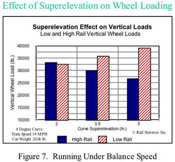
Figure 7 depicts the results of a vehicle dynamic simulation of vertical wheel loads for an 8-degree curve elevated at various elevations. These calculations are based on a 100-ton hopper car operating at a speed of 19 mph. With an elevation of roughly 2 inches, the vertical load on the low rail and high rail are nominally equal at 33,000 pounds. This represents equilibrium elevation. If the curve has 3.5 inches of elevation, the force on the low rail increases and the vertical force on the high rail decreases. If the curve has 5 inches of elevation, the high rail unloads to approximately 26,000 pounds, and the force of the low rail loads up to roughly 40,000 pounds. While all of these elevations are within the FRA Track Safety Standards, it is clear that if the curve had 5 inches of elevation, the risk of high rail wheel climb would be significantly increased, as the wheel looses about 25% of its vertical weight. This condition would be further exacerbated if there were a 1-inch track twist in the curve, which also is within FRA standards. Thus, when operating on over-elevated, but nonetheless FRA-compliant track, even nominal track twist variations can result in an increased risk of wheel climb derailments.
The Solutions
In an ever-changing rail environment, curve elevations need to be constantly assessed to prevent the development of adverse consequences. Train speed needs to be assessed realistically, and not simply based on timetable speeds. Engineering and Operating Departments need to work together to assess proper curve elevations. If low rail spalling persists, the curve is gaining elevation, or there have been wheel climb derailments, remediation is in order. Some possible solutions are:
- Decrease train speeds on the downhill side of ruling grades to make them more in line with the uphill train speeds.
- Normalize speed limits across a territory to eliminate unnecessary up and down changes in speed limits.
- Work with passenger train operators to reduce passenger train speed limits—even a nominal amount. Since the centrifugal force is a factor of the speed squared, a modest reduction in speed of 10 mph can dramatically improve the balance of vertical wheel loads for the heavier freight cars.
- Increase freight train speed limits.
- Re-elevate the curves based on realistic operating speeds, not timetable speed limits.
