
How Rail Grinding and Milling Affect Noise on Transit Systems
by Jeff Tuzik
A well optimized wheel/rail interface is a quiet wheel/rail interface. In the rail transit environment, there are many technologies and strategies to reduce wheel/rail-generated noise, and they tend to focus on reducing rail roughness. Standard rail grinding, acoustic rail grinding, rail milling, and specialized acoustic grinding machines are the tools of the trade, each with a specific use-case and each capable of producing varying acoustic roughness and noise outcomes.
Rail grinding and milling are standard and necessary maintenance activities. They are used to remove mill scale on new rail, implement specific profiles, restore profiles following wear, and remove or mitigate the severity of RCF (rolling contact fatigue) and other surface defects.
“Operations that aim to change the profile shape target a relatively high metal removal rate of one millimeter or more,” Briony Croft, Director, Sahaya Consulting and Acoustic Studio, told attendees at the 2025 Wheel/Rail Interaction Rail Transit conference. “Preventive grinding, on the other hand, targets a much lower level of metal removal, typically around 0.2 millimeters.” Acoustic grinding is a surface-polishing activity; the aim is to remove as little metal as possible—less than 0.1 mm—and leave the rail profile effectively unchanged.
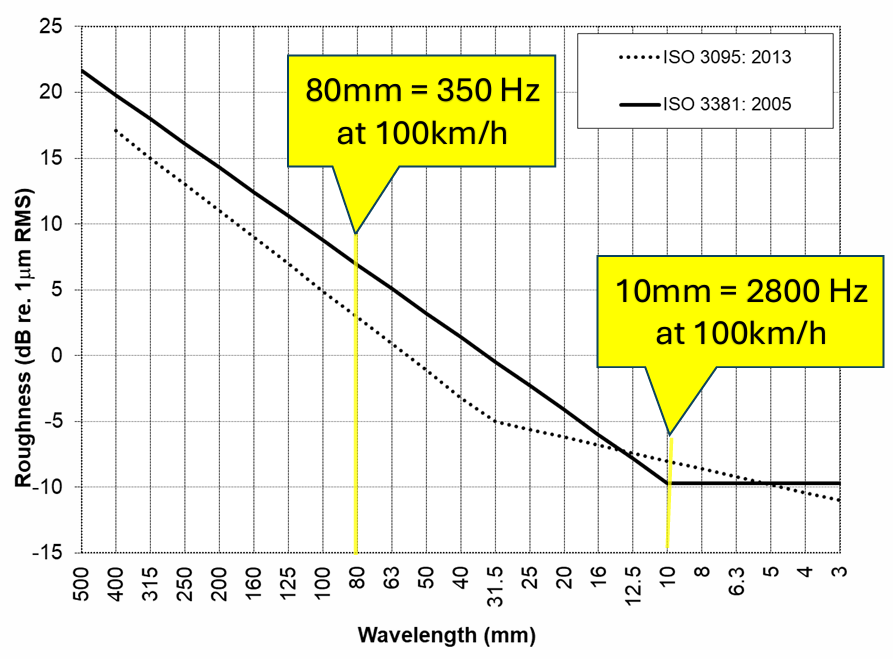
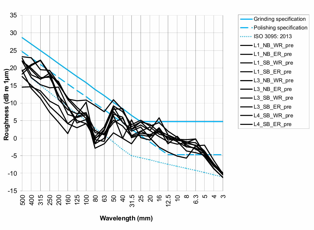
Figure 1 shows an example of a typical acoustic roughness graph; the wavelength in millimeters is on the X-axis and roughness in decibels on the Y-axis. “Roughness decibels loosely translate to acoustic decibels (noise), so a change in roughness decibels will approximately correlate to a change in noise level,” Croft said. The two lines on the chart represent different ISO standards. The solid line is ISO 3381 (2005); the dotted line is ISO 3095 (2013). The current version of ISO 3381 adopted the ISO 3095 reference roughness spectrum, which represents a very low level of rail surface roughness and, thus, track that is in very good acoustic condition.
The ISO standards were never intended to be used as grinding specifications, however. They were developed for testing vehicles, Croft said. The standard essentially represents rail that is so “smooth” that it contributes very little to the combined roughness in the wheel/rail interface, so that vehicle-generated effects can be more clearly identified.
Rail roughness wavelength, combined with the speed of the train, determines the frequency of the noise that is generated. For a transit system operating at 60 mph, for example, the area of interest falls between roughness wavelengths in the 10-mm to 80-mm range (as indicated by the yellow lines in Figure 1). “Between these lines is where we’re interested in potential noise effects,” Croft said.
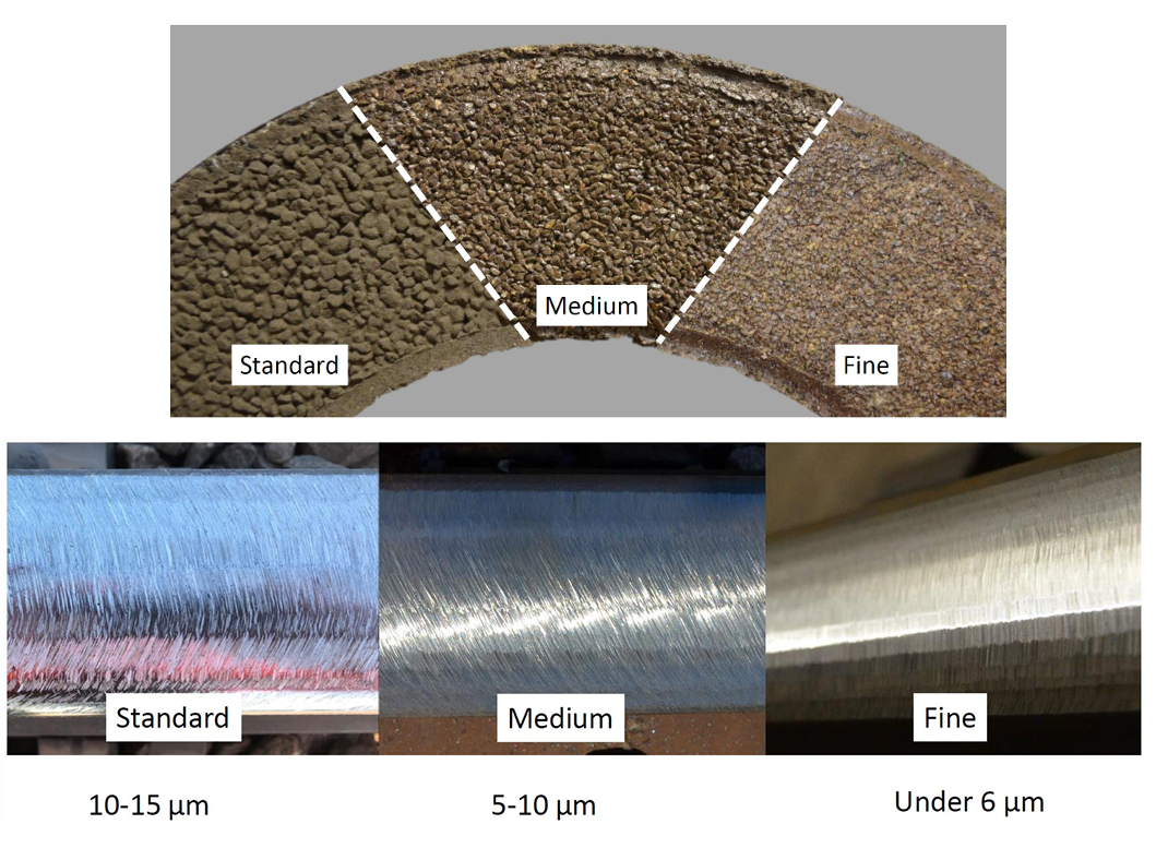
Figure 2 shows a comparison of grinding-stone grit (standard/low-grit, medium, and fine/high-grit) and the associated post-grind finish that can be achieved by each stone. “You can’t really tell how much noise a rail is going to make just by looking at surface micro-roughness, but it’s nonetheless an important measurement to make, and easily done via a handheld surface measuring device,” Croft said.
Wheel Roughness
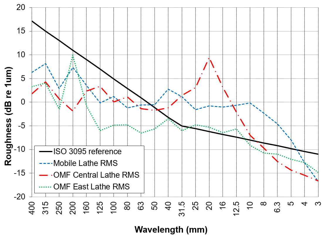
In wheel/rail interaction, no component exists in a vacuum. Roughness at the wheel/rail interface is the combined result of both wheel and rail characteristics. Figure 3 shows an acoustic roughness graph with the ISO 3095 reference. The graph shows the acoustic roughness of three wheels measured immediately after re-truing (each wheel was machined by a different lathe). As indicated by the dashed red line, one wheel has peak at 20 mm. “That’s right in the area of concern for noise, and it’s quite high above the reference spectrum,” Croft said. “The blue wheel has broadband high roughness in the frequency range of interest. Only the green wheel shows what I’d call a good outcome.”

However, once these wheels went into service, the roughness peaks wore in very quickly, Croft said. The wheels shown in Figure 4 are not the same wheels from Figure 3, but they were turned by the same lathe that introduced the concerning 20-mm peak. These wheels, which were measured 3,300 miles after being turned, fall well within or below the ISO 3095 reference. “It’s quite common on transit systems that rail roughness is more important for noise generation than wheel roughness, particularly on vehicles with disc brakes and when the rail steel is relatively harder than the wheel steel,” she said.
Standard (Non-Acoustic) Grinding: Comparisons
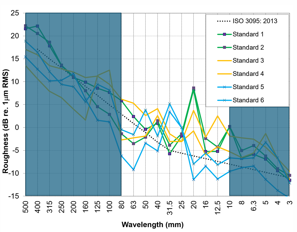
Figure 5 shows acoustic roughness outcomes measured immediately after grinding on six rail transit systems (from North America and Australia). The chart includes examples of standard maintenance/preventive grinding using medium-grit stones. The characteristics and magnitude of the various peaks between 20-mm and 50-mm wavelengths are a function of grinding speed, grindstone diameter, and module amperage (the downward force applied to each grind module), Croft said. As a result of this variability, some peaks emerge as much as 15 dB above adjacent bands. “The results here are quite good for standard grinding, but it’s worth noting that more aggressive profile grinding using coarse/ low-grit stones would produce significantly higher roughness.”
Acoustic Grinding: Comparisons
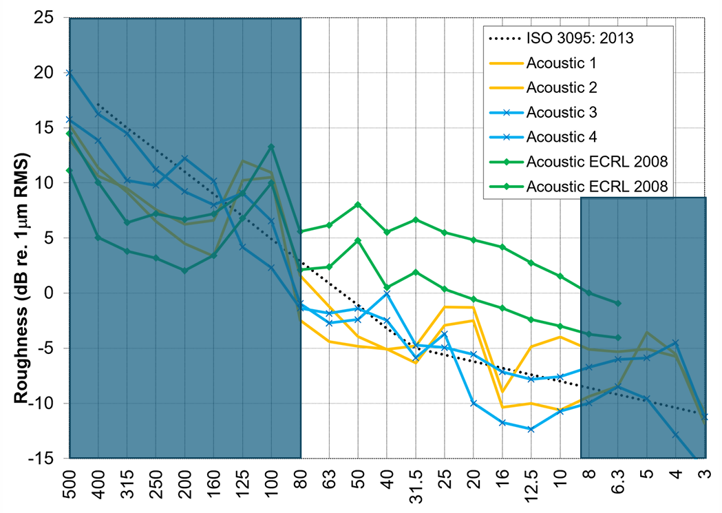
There has been a lot of work, over the years, to push standard grinders to the edge of their capabilities in order to produce better acoustic grinding results. Figure 6 shows some of these results. The green lines represent early acoustic grinding efforts in Australia. “This was a project that attempted to develop an acoustic grinding process using the available standard grinding equipment,” Croft said. The objective was to shift the typical grinding-induced roughness peaks (usually in the 20-mm to 50-mm frequency) to the left, or to longer wavelengths, which are closer to the ISO 3095 reference. “They managed to shift the peaks out to 100 mm,” she said. “And in practice, the roughness at shorter wavelengths wore down quite quickly as well.”
The yellow and blue lines represent North American transit systems experimenting with standard grinding equipment but much higher-grit (finer) stones. While there is a good deal of variation in the results, they show that roughness measurements in the area of concern for noise generation (10 mm to 80 mm) are within 5 dB of the ISO 3095 reference line.
Milling: Comparisons
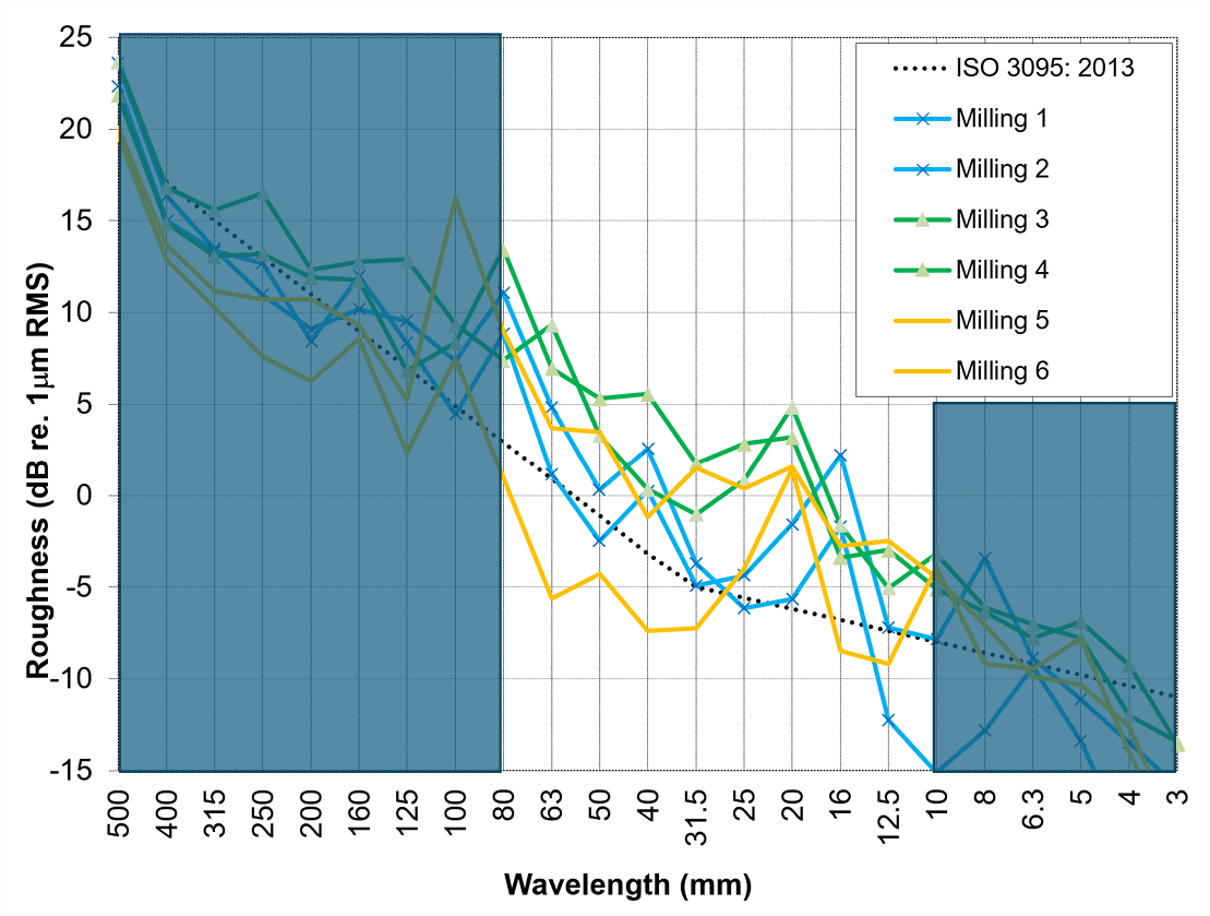
The acoustic roughness graph in Figure 7 shows the results of milling on several Australian transit properties. “It’s very important to note that these results are all from a milling machine that doesn’t have a polishing stone,” Croft said. Many milling machines include a polishing stone or a follow-up polishing process, similar to a high-grit grindstone, that rotates parallel to the track, rather than perpendicular (as in standard rail grinding) to leave behind a highly polished and non-faceted surface finish. “Without the polishing step, you can see that outcomes are not particularly smooth,” she said. “The decibel peaks are not as distinct as in a standard grinding scenario and are more broadband.” The outcomes are also quite variable, with peaks in the area of concern for noise as high as 10 dB above ISO 3095. Clearly, the polishing step is of critical importance to achieve optimal acoustic results from milling.
“New” Technology in Acoustic grinding
Although unavailable or only recently introduced to North America, there are a number of grinding machines and technologies that are particularly, but not exclusively, designed to operate in an acoustic grinding mode. One such example is Rail Technology’s Silent Track grinder, which, unlike traditional rail grinders, uses longitudinally reciprocating grindstones that leave a finish that looks less like the arcing pattern of a standard grind signature and more like that of a post-milling, post-polishing surface. Data provided by Rail Technology from yard trials shows an absence of sharp peaks and thus of tonal noise, Croft said. The acoustic roughness is also below ISO 3095 for the entire spectrum.
Vossloh developed the HSG-City grinder, which leaves a distinctive cross-hatched grind signature due to the shape and orientation of the grindstones. Additionally, the stones rotate passively, driven instead by the grinder’s forward motion. Acoustic roughness data provided by Vossloh shows the average measurements from two different sites with lines indicating measurements taken at two days, two weeks, and five weeks post-grind. Like the Silent Track results, the HSG-City results show no sharp peaks in the roughness spectrum and roughness decibels at or below ISO 3095. “I can’t speak to [these newer technology grinders’] efficacy on harder rail steels or at higher rates of metal removal,” Croft said, “but it speaks to the fact that sub-ISO 3095 acoustic grinding results are certainly achievable.
The Plasser Atmo block grinder is another grinding technology that has operated for many years in the EU, but is not currently available in North America. Like the Silent Track grinder, the Atmo uses longitudinally reciprocating blocks, and is therefore expected to give a good acoustic outcome.
Worn-in Roughness
All of the previously shown acoustic roughness graphs are from measurements made very shortly after grinding/milling/acoustic grinding. But longer-term acoustic roughness measurements can look quite different once the rail has worn in, Croft said. In standard or softer rails steels (around 260 HB) many of the grinding-induced peaks in the spectrum of interest for noise (20 mm – 50 mm) can wear down to below the ISO 3095 reference. The same is true for the entire range of the 10-mm to 80-mm wavelengths of concern for noise.
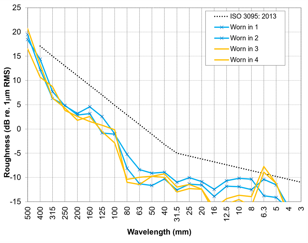
Figure 8 shows data from two transit systems with very low acoustic roughness on well-worn-in rail. “It’s nice to work on a system where the rail gets smoother over time, but that doesn’t always happen,” Croft said. The particular mechanisms that cause some systems to get smoother over time and others to get rougher are not well understood.
Figure 9 shows worn-in roughness data from Seattle’s Sound Transit, which uses harder rail steels. “Sound Transit is one of those systems where roughness increases over time, and grinding and polishing tends to reduce roughness and noise,” Croft said. Elsewhere, such as in Sydney, grinding tends to increase roughness and noise relative to the worn-in state. Unfortunately, the data presents no clear answers on this paradoxical-seeming behavior.
Modelling Rolling Noise
To develop a quantifiable and objective sense of how various grinding technologies and strategies affect rolling noise, Croft modelled a number of scenarios using Train Noise Expert (TNE) modelling software. The scenarios she modelled were:
- Worn-in rail
- A rough reprofiling grind
- Acoustic grinding using standard rail grinders equipped with fine/high-grit stones
- Acoustic grinding using “specialized” equipment
All of the models were calculated with a metro train on resilient direct-fixation slab track, running at 100 km/h (≈62 mph) with wheels in good condition. The only variable (in this case) is the roughness input, Croft said.
The roughness inputs were as follows:
- Worn-in measurements were taken directly from measurements on a transit system.
- Roughness measurements were taken from the same transit system three weeks after grinding to install a target rail profile.
- Acoustic grind data was taken several days after acoustic grinding with fine stones.
- “New technology” inputs were based on a combination of Rail Technology’s Silent Track and Vossloh’s HSG-City data.
- Wheel roughness was based on a median of 50 wheels with 1,000 to 40,000 accumulated miles since trueing/machining.

The noise predictions generated by the TNE model can be seen in Figure 10. All dBA figures indicate equivalent average noise (LAeq) for a single passby measured 15 meters from the vehicle. The worn-in scenario is the quietest at 74.9 dBA; the new technology and acoustic grind scenarios are only 0.5 dBA apart, coming in at 77.2 dBA and 77.7 dBA. The rough profile grind scenario was modelled at 86.4 dBA, an 11.5-dBA increase over the worn-in scenario. “The 11.5-dBA difference between the worn-in and rough reprofile scenarios means the rough grind scenario would be perceived as twice as loud,” Croft said. Indeed, the site that these measurements were taken from generated noise complaints from residents living up to 2 km (1.2 miles) away.
Croft didn’t model a milling scenario but said the outcome—assuming the milling process included a polishing stage—should be similar to the new technology/acoustic grind scenarios.
Takeaways? It’s important to understand that profile and heavy corrective grinding are entirely different processes than acoustic grinding. It’s best to think of these as separate steps altogether to maximize the efficacy and outcomes of each step, Croft said. And while most grinding specifications don’t directly address noise outcomes, there is a wide variety of technologies and methodologies available to mitigate acoustic roughness. Achieving good results with standard grinding equipment is possible, but it requires fine stones plus additional time, cost, and effort, including careful quality control processes. The good news is that some technologies, which have long been part of the maintenance toolbox in other parts of the world, are now becoming available in North America.

Jeff Tuzik is Managing Editor of Interface Journal
This article is based on a presentation made at the 2025 Wheel/Rail Interaction Rail Transit Conference.
All images are courtesy of Briony Croft except where otherwise noted.