
Track Structures and Components: Design Specifications to Safety Limits
by Jeff Tuzik
The track system is a remarkable feat of engineering. To the uninitiated, it can appear simple, mundane. But those charged with constructing or maintaining it know that it’s a marvel of design, that has been continuously updated since its inception roughly 200 years ago.
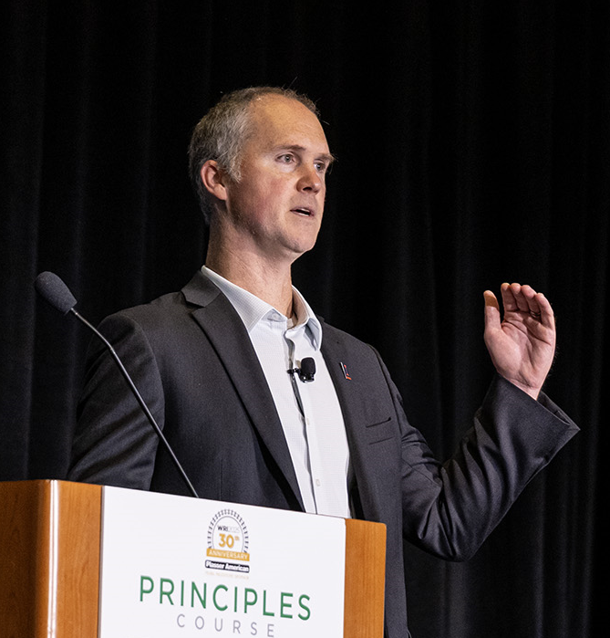
“We take loads that are near the yield strength of steel at the wheel/rail interface, and by the time the forces are transmitted and attenuated through the track and subgrade, they’re on par with the force of a footstep,” J. Riley Edwards—Assistant Professor in the Rail Transportation and Engineering Center (RailTEC) at the University of Illinois Champaign-Urbana—told attendees at the 2025 Principles of Wheel/Rail Interaction Heavy Haul Conference. Designing and maintaining an optimal track system is a battle that’s won or lost at the interfaces—not just the wheel/rail interface, but every interface between the track and track components, tie and ballast, ballast and subgrade, he said.
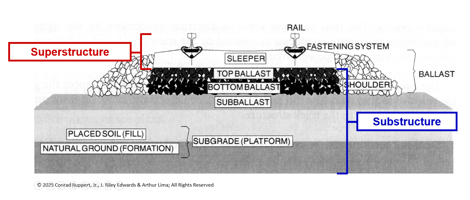
The track superstructure, which can be thought of as the “visible” portion of the track, begins where the wheel meets the rail and ends at the base of the crosstie (see Figure 1), Edwards said. “At this state, we’re attenuating pressures of ≈120,000 psi at the contact patch down to ≈65 psi at the base of the crosstie to ensure that we don’t crush the ballast.” The track substructure, which is comprised of the layers from the bottom of the tie down to the subgrade, further dissipates load pressures, from ≈65 psi to <18 psi (i.e. the bearing capacity of the natural subsoil).
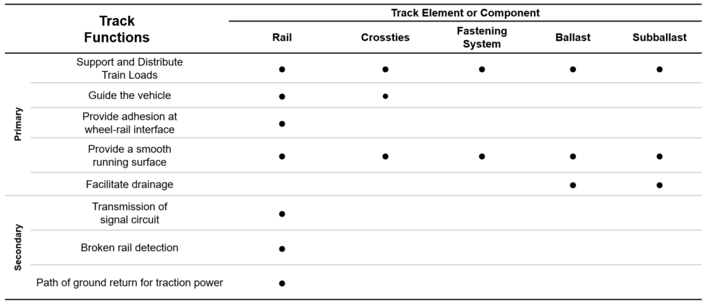
Every component that makes up the track and track structure fulfills one or many functions to facilitate the dissipation of energy from a passing train and to ensure that the system operates optimally. Figure 2 illustrates a few of these primary and secondary functions. “Take just the rail, for example. It is the first and most critical safety component of the system. It supports the train load; it provides the ‘guidance’ function for the train; it carries the signaling circuit,” Edwards said. The rail is the preeminent component in the interface.
The Rail
In North America, AREMA standard 136RE and 115RE account for the majority of the new rail rolled and installed; 136RE accounts for roughly 60% of the NA total and is very common in heavy haul applications; 115RE accounts for roughly 20% where it is most frequently found in transit applications, Edwards said. In addition to meeting the precise specifications of the AREA (or other) standards for the rail type, rail is also engineered for specific metallurgical properties, specifically high wear resistance, high fatigue resistance, and high ductility/yield point.
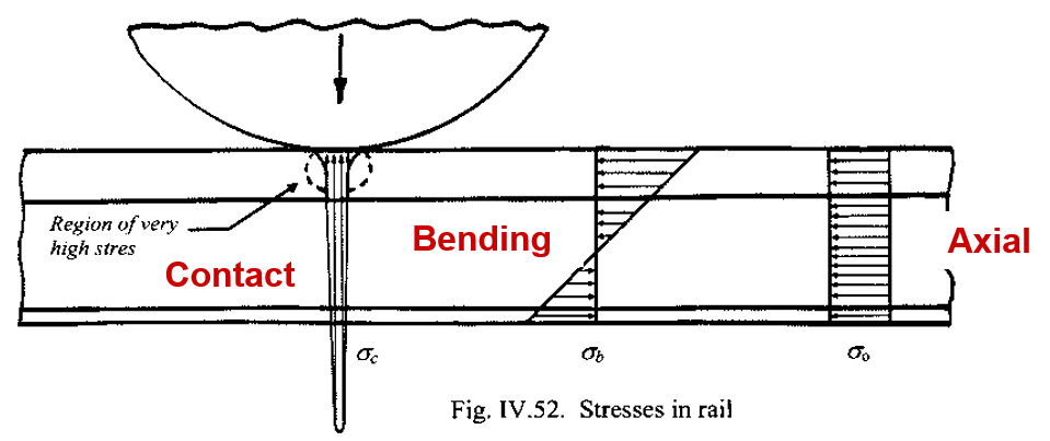
Rail itself is subject to three primary interfacial stresses: contact stresses caused by static and dynamic wheel loads at the wheel/rail interface, bending stresses also caused by wheel loads and by non-uniform temperature changes, and axial stresses caused by uniform temperature changes (expansion and contraction of the rail) which can be due to environmental conditions and/or dynamic loading, Edwards said (Figure 3 illustrates these stresses). The forces that produce these stresses (vertical, lateral and longitudinal) and are generated by a combination of static, dynamic, and impact loading, are fundamental to safe track design and train operations.
All rail is also subject to residual stress—stresses formed as part of the manufacturing and rolling processes. “Unfortunately, we don’t have a very good way of estimating residual stresses. So, when designing a rail system, we have to include a very comfortable safety margin to account for it.”
Axial stresses, particularly in continuous welded rail (CWR), can cause rail breaks (pull-aparts) and track buckles (sun kinks) when there is a large difference between the stress-free temperature, known as the rail neutral temperature (RNT) and the actual rail temperature. Railroads have gotten much better at managing rail stresses, but RNT in CWR remains a topic of ongoing study (and consternation), he said.
The Tie
Forces transmitted into the rail don’t stay in the rail. Much of that energy flows into the ties, which, like rails, serve many functions. They (along with fasteners) maintain gage, distribute wheel loads from the rail to the ballast, and anchor the track against deviations in track geometry. The rail-to-tie interface is often mediated by tie plates (for timber ties) which distribute the loads transmitted by the base of the rail over a larger surface. Resilient rail pads serve a somewhat similar function (evening out contact pressures) in concrete tie applications with high rates of rail seat abrasion and rail damage/breaks (see Using Elastic Components to Improve Rail, Tie, and Ballast Life for more information).
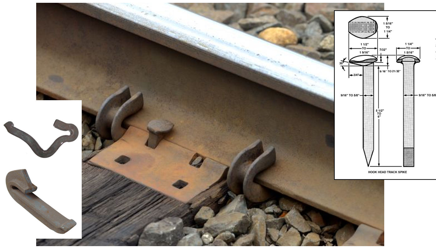
Timber ties account for ≈90% of all crossties in the United States, and cut spikes and anchors (see Figure 4) make up ≈95% of all timber-tie fastening systems. Concrete ties, which account for ≈8% of all crossties in the U.S., require the use of an elastic fastening system. Figure 5 shows one such example of elastic fasteners (clips) that is common in North America. These fasteners generally provide ≈5,000 lbs of clamping force per rail seat, which obviates the need for rail anchors, which are typically seen in wood tie applications, for lateral, vertical, and rotational rail restraint. In addition to providing support and restraint for the rail, ties are also the interface between the forces and loads of the train and the ballast.
“The ballast/sub-ballast are the final stages in load distribution,” Edwards said. Ballast itself is ideally made up of relatively large particles that interlock well. There should also be voids between interlocked particles to facilitate drainage and thus mitigate fouling. Sub-ballast, on the other hand, is made of finer particles and packed much more densely. The sub-ballast should be largely water-impenetrable; the slope of the right-of-way should carry drainage away from this layer, Edwards, said. “That’s the ideal, but it’s not always the case in practice.”
Design and Safety
The strength and resiliency built into the track system by virtue of the various components working in concert is one of the primary considerations in curve design: in terms of degree of curvature (or curve radius), allowable curve speed, and curve superelevation. The balanced condition for a train navigating a curve is an ideal scenario in which a vehicle is moving at the perfect speed, degree of curvature and superelevation such that curving forces produce equivalent forces on each rail, Edwards said. In real-world operations, this isn’t always the case.
However, the inbuilt track strength is such that a level of allowable unbalance, or cant deficiency, is part of the equation. This is typically 1 to 2 inches (for heavy haul operations). Cant deficiency does not actually exist in track, but the train operates as though it does. “Well designed and maintained track can resist very high lateral loads, which means we can safely navigate curves at speeds in excess of their balance speed.”
It’s also important to note the difference between design specifications and regulatory safety limits—not only in curve superelevation, but in all track components and their impact on track geometry. Track geometry defects, such as defined by the FRA Track Safety Standards and the Track and Rail and Infrastructure Integrity Compliance Manual can be caused or influenced by any component in the track system. “Any perturbation in geometry introduces additional dynamic loads in the track that can cause vehicle and component damage, poor ride quality (for passenger applications), and in the worst case, derailments,” Edwards said.
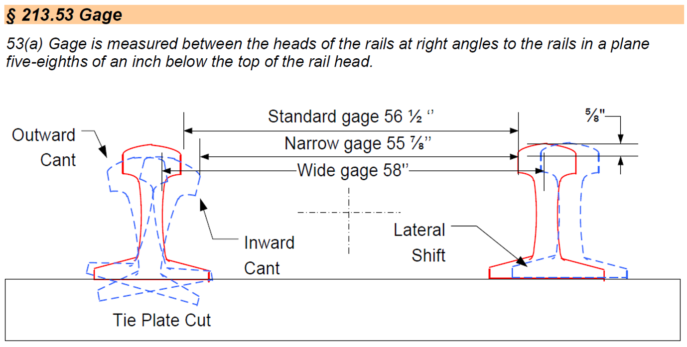
Wide gage, for example (see Figure 5 for an excerpt from the FRA Track Safety Standards) can be caused by issues such as tie plate cutting (in wood ties), broken clips (leading to poor cant/gage restraint), broken rail anchors and/or cut spikes (leading to potential lateral rail shift), he said. Regardless of the culprit, a severe enough defect will trigger a slow or stop order until the defect is fixed.
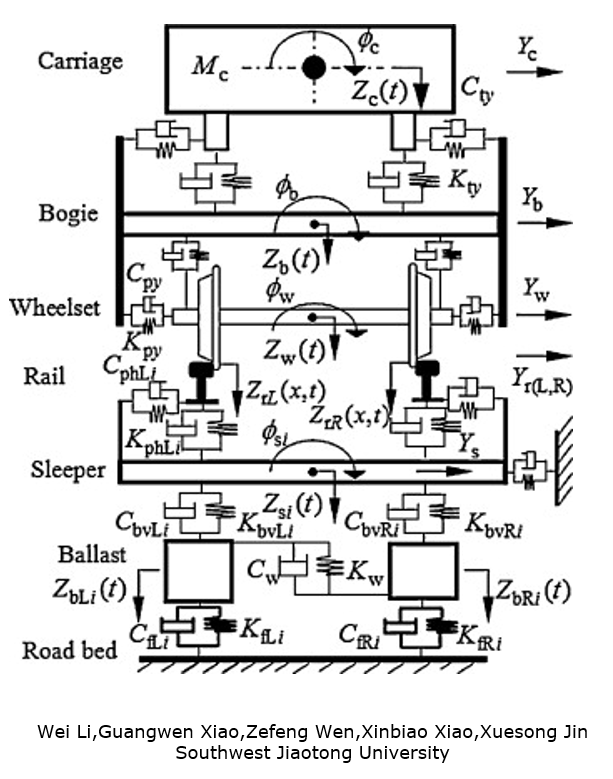
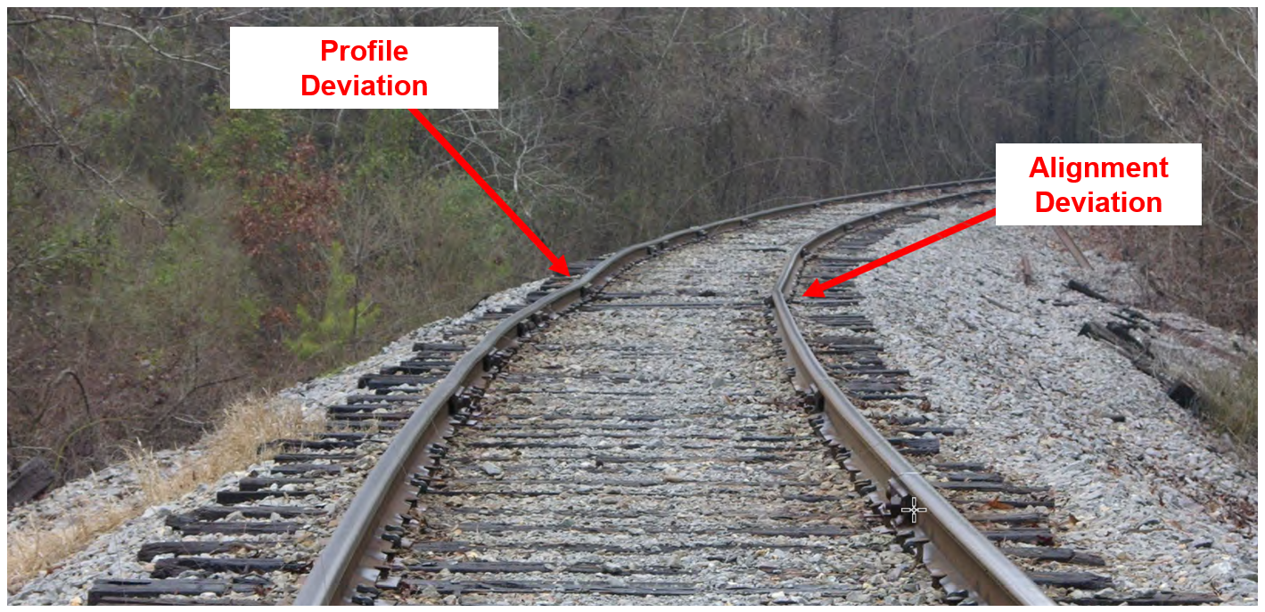
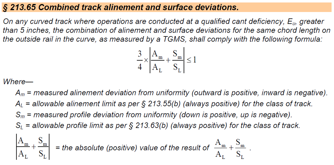
Figure 6 shows a significant profile (vertical alignment) deviation, in this case caused by permanent settlement in the track substructure. FTA safety limits for Class 4 track (60 mph freight / 80 mph passenger) allow for 2 inches of profile deviation at the mid-ordinate of a 62-foot chord. Here, the profile deviation coincides with a horizontal alignment defect at roughly the same location on the low rail. The safety limit for alignment deviation in curves is measured from the mid-ordinate of a 31-foot chord; for Class 4 track, this limit is 1 inch. However, due to the interplay of multiple defects like this, the FTA threshold for combined surface and alignment defects is significantly more complex to calculate (see Figure 7 for details).
As Figure 8 indicates, the vehicle and the track superstructure and substructure are part of a complex and dynamic system—one that is difficult to model. But a well-researched (and long-practiced) list of design fundamentals, maintenance practices, and safety thresholds help reduce the complexity of the system and break it into more manageable segments and components.
This article is one of a series on the fundamental aspects of track and vehicle design and maintenance that is presented through Wheel-Rail Seminars’ Principles of Wheel/Rail Interaction.

Jeff Tuzik is Managing Editor of Interface Journal
This article is based on a presentation made at the 2025 Wheel/Rail Interaction Heavy Haul conference.
Images are courtesy of J. Riley Edwards except where otherwise noted.