
The Theory & The Praxis: An Introduction to Wheel/Rail Interaction. Part 1.
by Jeff Tuzik
Your phone rings on a Tuesday morning. There are a couple of double-stack well cars on the ground.
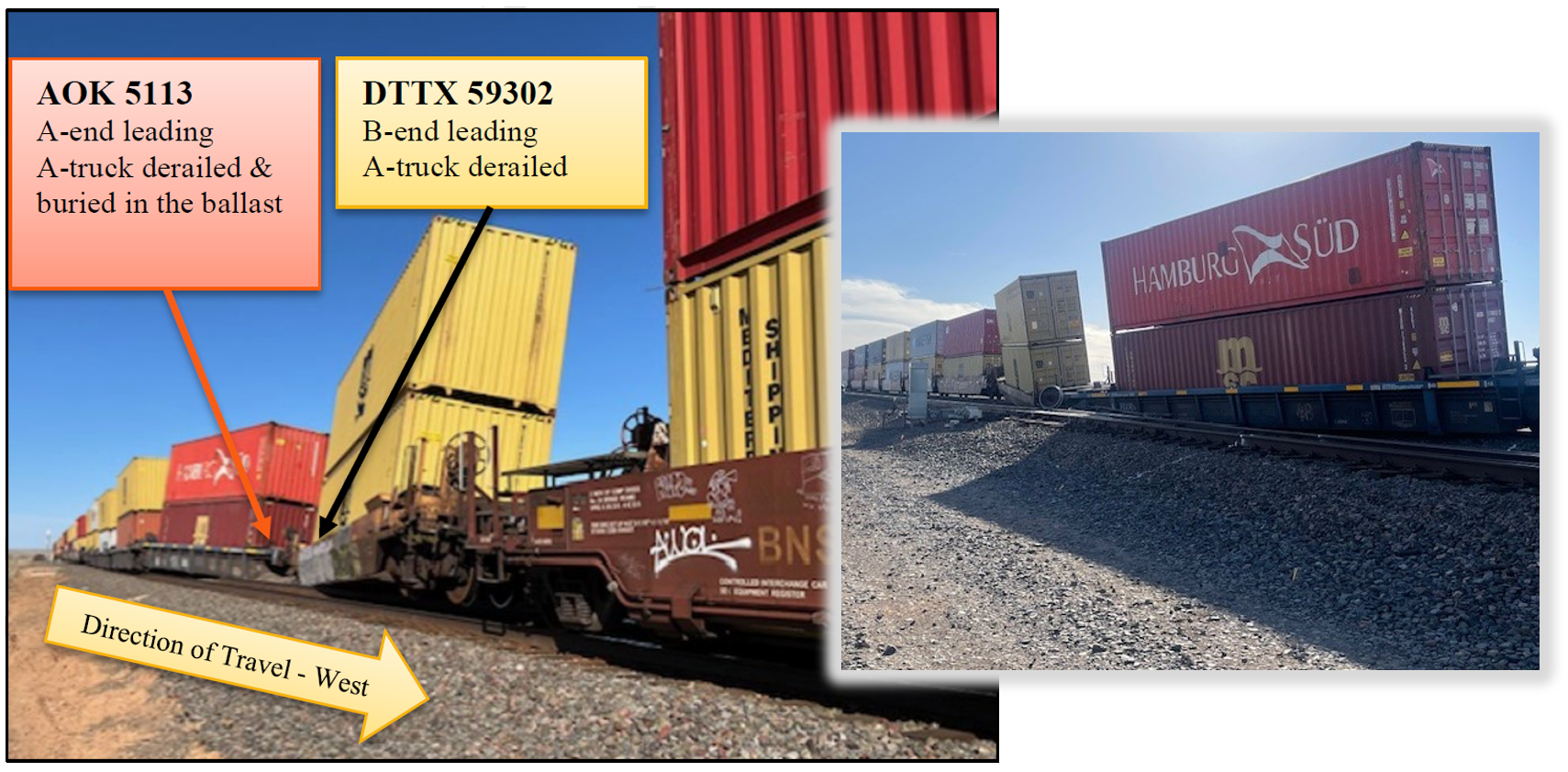
That’s the kind of wakeup call a derailment investigator typically gets when something has gone badly awry, and the search for what happened and why has begun, David Casaceli, Railroad Accident Investigator at the National Transportation Safety Board (NTSB) told participants at the opening of the 2026 WRI Heavy Haul Principles Course, which was sponsored by the National University Rail Center of Excellence.
“The principles of wheel/rail interaction explain why wheels stay on the track, and why, sometimes, they don’t,” Casaceli, who moderated and led the course, said. Understanding and optimizing wheel/rail interaction is integral to both track and vehicle performance, and to maintenance strategies and practices.
For such an important concept, it’s one that can be overlooked or not fully appreciated—even by people with a lot of field experience under their belts. This is primarily due to the multi-disciplinary nature of vehicle/track interaction and wheel/rail interface engineering, and the fact that the practical application of these principles requires cooperation and coordination between multiple departments in a railroad. Another stumbling block is that wheel/rail interaction concepts can seem abstract or theoretical, rather than practical.
Derailments, though, are not theoretical. They are the result of the practical application of multiple systems and circumstances interacting in such a way as to overcome the designed geometry, and gravity, to knock a train off the track. So, Casaceli and the other presenters used a case study of a derailment to frame the WRI Principles course and contextualize the various elements of vehicle/track interaction.
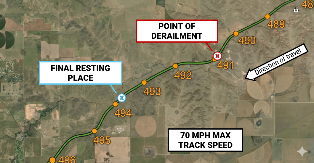
Casaceli metered out the salient information from the investigation throughout the course. Slowly piecing it together, as an investigator at the site would do. The first order of business was to determine the point of derailment (POD), which was found near milepost 491 in a 1.9-degree-righthand curve. The final resting place of the derailed cars was near milepost 494. This means that the cars were dragged for several miles before it was apparent that a derailment had occurred (see Figure 1).
One of the first principles of wheel/rail interaction is the primacy of lateral and vertical forces, the L/V ratio, acting on the wheel/rail interface (see The How and Why of L/V-based Thresholds for more information). The L/V ratio is typically measured against an L/V threshold (the Nadal limit, for example) that is used to assess the risk of wheel-climb derailment, based on wheel/rail contact geometry and coefficient of friction at the contact patch. As lateral forces increase or vertical forces decrease (or both), the L/V ratio increases and moves closer to the threshold, Casaceli said. There is also an L/V threshold for rail rollover, which is a function of the base/height ratio of the rail per wheel/rail contact point.
“Let’s start our investigation from the ground up.” Casaceli said.
Track Structure and Components
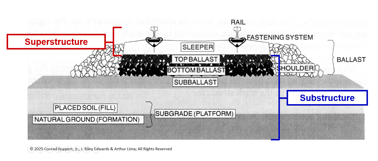
The track consists of two primary sections: the superstructure and the substructure. The track superstructure consists of the “visible” portion of the track, beginning where the wheel meets the rail and ending at the base of the crosstie (see Figure 2), said J. Riley Edwards, Assistant Professor in the Rail Transportation and Engineering Center (RailTEC) at the University of Illinois Champaign-Urbana. “On the superstructure, we’re attenuating pressures of ≈120,000 psi at the contact patch down to ≈65 psi at the base of the crosstie to ensure that we don’t crush the ballast.” The track substructure—which includes the top ballast, bottom ballast, subballast, fill, and natural ground—further dissipates load pressures, from ≈65 psi to <18 psi (i.e. the bearing capacity of the natural subsoil).
The rail, of course, is the preeminent component of the wheel/rail interface, Riley said. “It is the first and most critical safety component of the system; it supports the train load; it provides the ‘guidance’ function for the train; and it carries the signaling circuit.” (see Track Structures and Components: Design Specifications to Safety Limits for more information).
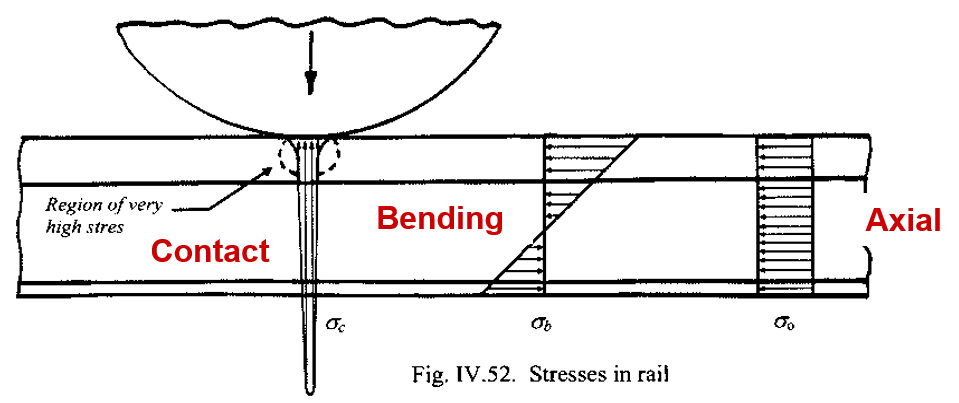
The rail is, unsurprisingly, subject to tremendous forces and stresses. The three primary stresses are contact stresses caused by static and dynamic wheel loads at the wheel/rail interface, bending stresses also caused by wheel loads, and by non-uniform temperature changes, and axial stresses caused by uniform temperature changes (expansion and contraction of the rail due to environmental conditions and/or dynamic loading [see Figure 3]). These stresses are imparted by a combination of vertical, lateral, and longitudinal forces generated by a combination of static, dynamic, and impact loading, Riley said.
Rail is also subject to residual stress—stresses formed as part of the manufacturing and rolling processes. “Unfortunately, we don’t have a very good way of estimating residual stresses. So, when designing a rail system, we have to include a very comfortable safety margin to account for it,” Edwards said.
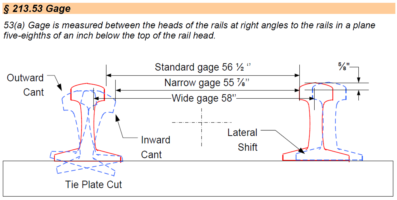
Moving down, the tie and its components are the next “layer” of the track superstructure. Ties (and fasteners) maintain gage, distribute wheel loads from the rail to the ballast, and anchor the track against deviations in track geometry. The strength and resiliency of the track is dependent on the anchoring force of ties and fasteners. Degradation or failure of these components can cause outward or inward rail cant and lateral rail shift, both of which can lead to gage defects and ultimately derailment conditions, Edwards said (see Figure 4).
The track substructure (the ballast and below) is the final stage of load distribution. Ballast is also responsible for supporting and anchoring the ties. In cases where the ballast is inadequate to support the tie (and the forces imparted by wheel/rail interaction), ties can shift vertically and/or laterally leading to profile and alignment geometry defects.
The Derailment
At the point of derailment in the case study, the rail was found to be in good condition. The ties (timber ties with cut spikes and anchors) were similarly judged. Design specifications indicate that the track should have 4⅜ inches of superelevation. However, most of the body of the curve measured ≈5½ inches. It was over-elevated, but not severely. Wheel marks were evident on the field side of the high rail and in the middle of the gage. “Putting this all together, we now know that this was a high-rail-wheel-climb derailment,” David Casaceli said.
Vehicle Types and Components
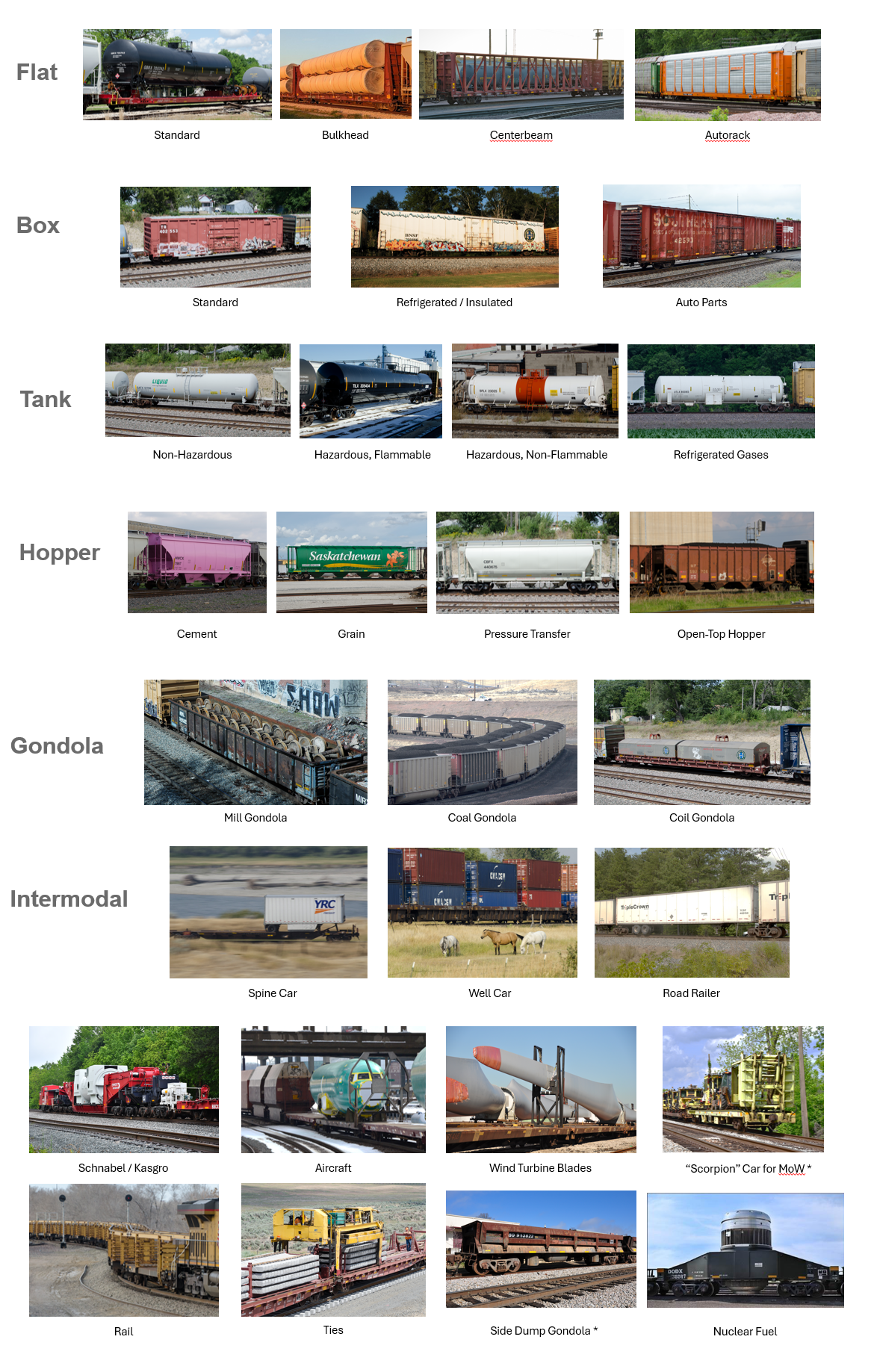
Track is one side of the wheel/rail interaction puzzle, the wheel, truck, and vehicle are the other. Suspension design and performance plays a critical role in shaping and reacting to dynamic forces at the wheel/rail interface. The case study features double-stack well cars, a very common car type. But there are many others moving about the Class 1s: flat cars, box cars, tank cars, hopper cars, gondolas, and intermodal equipment (well cars fit into this category). (See Figure 5). There is also an array of specialty cars, such as cars designed to carry long lengths of continuously welded rail (CWR) which span multiple flat-type cars, heavy and rigid nuclear fuel cars, Schnabel cars which carry very heavy or oversized loads by distributing the weight across multiple span bolsters, and many more.
Every car is rated on gross rail load (GRL), which is a combination of the car’s light weight and the load limit. Track infrastructure determines the maximum GRL for any given line. For example, 286k (286,000 pound GRL) is standard for Class 1 mainline track, while some specialized corridors are rated up to 315k. “It’s important to remember that there can be a very big difference between your empty weight and your loaded weight, up to a 6x difference,” said Darrell Krueger, Director of Technical Research and Development at BNSF. This has significant implications for truck and suspension design, and for wheel/rail interaction in general.
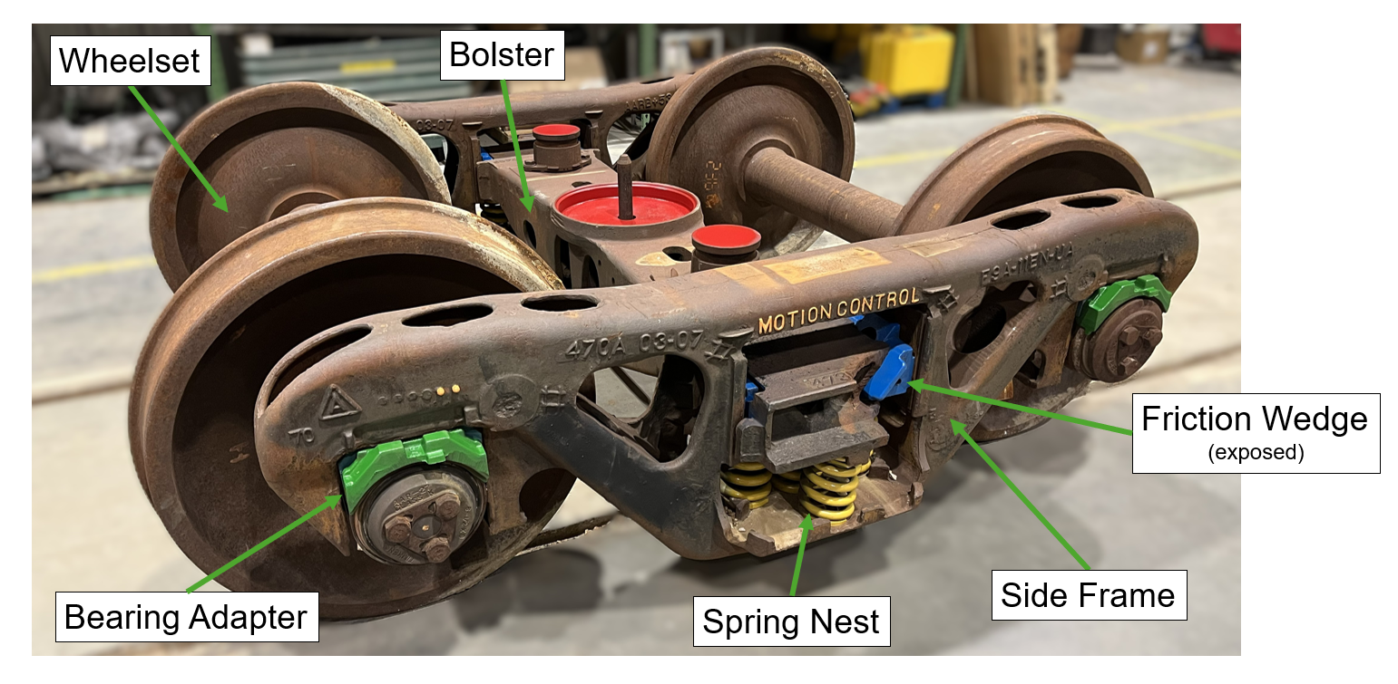
Most cars on Class 1 railroads run on industry-standard three-piece trucks (see Figure 6). The carbody contacts the truck at the centerbowl (the primary contact and swivel) and the side bearings (which provide truck yaw damping). The springs and friction wedges are the suspension components. “This isn’t high technology, but it’s good technology; a simple and rugged design made of simple components,” Krueger said.
A rail car and its truck(s) make up a spring-mass-damper system. The truck, alone, is made of multiple spring-mass-damper systems. “All these systems have resonance or a ‘natural frequency,’ so there are many resonances that can be excited by moving down the track; the three-piece truck is designed to avoid them.” Krueger said.
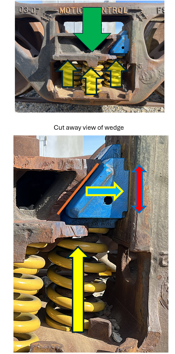
Primary damping in the truck is provided by the springs and friction wedges. As the springs are compressed, the geometry of the bolster is such that increasing lateral force is applied to the friction wedges, causing them to create drag on the bolster pocket side walls (see Figure 7). To optimize the suspension for both loaded and unloaded cars, there are springs of differing stiffness in the spring nest, Krueger said. Softer springs are engaged in an unloaded state, and much stiffer springs engage in a loaded state.
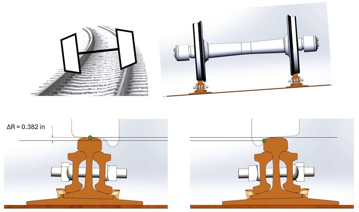
Wheelsets (and thus trucks) are also responsible for steering through curves. Steering itself is facilitated by the conical shape of the wheel. In simple terms, when a wheelset shifts laterally the wheels develop a rolling radius difference. In a curve, the low rail wheel has a smaller rolling radius than the high rail wheel (see Figure 8). Because both wheels rotate at the same rate, the high rail wheel travels further than the low rail wheel and thus the wheelset navigates the geometry of the curve. “Once again, this ‘simple’ truck is designed to facilitate and optimize very complex interactions,” Krueger said.
The Derailment
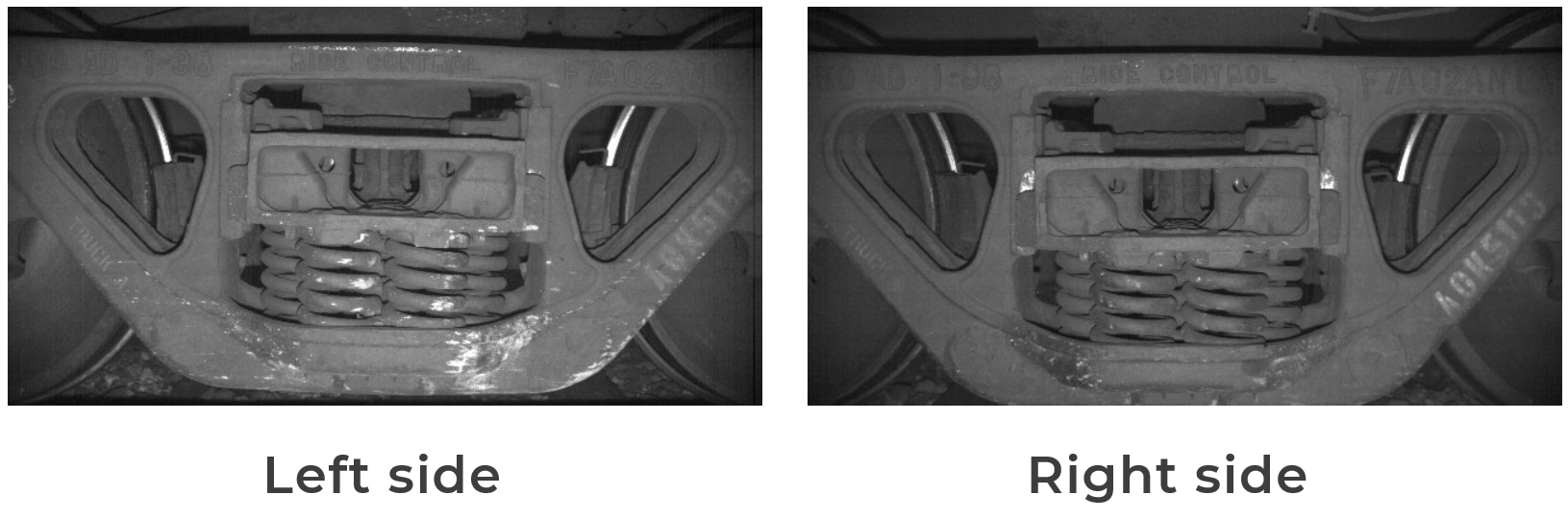
In the derailment, the first wheels to derail were on the A end of car AOK 5113. The three-piece truck remained “mostly intact” throughout the derailment, David Casaceli said. Wedge rise (i.e. primary suspension wear) was found to be 1.5 inches (on the right side) and 1.2 inches (on the left side), both of which are comfortably below the limit of 1.82 inches. Automated-inspection images showed that six to eight weeks before the derailment, abrasion appeared on the side frames and springs of all trucks on the left side of AOK 5113 (see Figure 9). Initial examination of the containers from first car to derail showed evidence of potential load shift and load imbalance. “On the mechanical side, there are some curious findings, but nothing damning,” Casaceli said.
“Understanding the track space and the wheel space lets us focus right there on the contact patch. Not above or below, just the wheel/rail interface.”
Wheel/Rail Contact
One core principle of wheel/rail interaction is the ratio of lateral to vertical forces at the wheel/rail interface.
“First, I want to make sure we really understand steering forces. We know that difference in wheel radius (rolling radius difference) gives us steering. We know that when we have a wheel climb, the wheel climbing the high rail is suddenly going to have a much bigger radius once the flange is on the rail. So, why doesn’t it steer itself back and rerail?” said Kevin Oldknow, Associate Professor at Simon Fraser University.
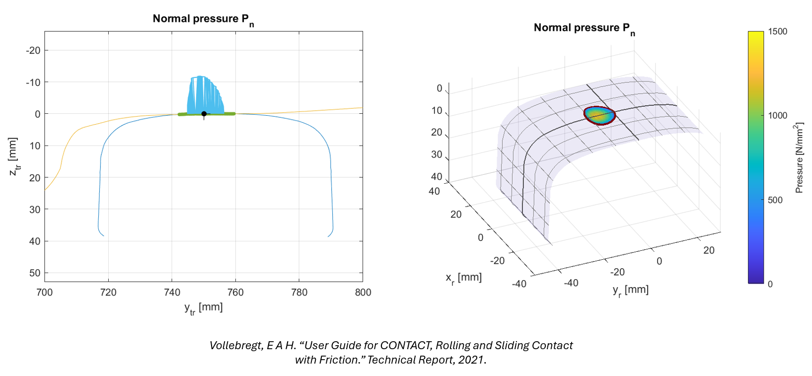
Answering that question requires a deep dive into the contact patch. Contact pressure and geometry are the first fundamental. At this point, the wheel and rail are in contact with each other, but nothing is moving—static shapes with a load applied. This is the contact patch, often described as roughly the size of a dime, Oldknow said. As load is applied, the two bodies (wheel and rail) elastically deform, and the size of the contact patch increases (see Figure 10). “It’s important to note [in the quasi-Hertzian case of wheel/rail contact under load] that the point of maximum shear stress is actually a few millimeters below the surface of the rail.”
However, from a practical standpoint, wheel/rail contact isn’t always single-point contact. Two-point contact and conformal contact are non-Hertzian, and significantly more complicated.
Traction and creepage are the second fundamental. This is where movement enters the frame. “Creepage within the contact patch can include three types: lateral, longitudinal, and spin,” Oldknow said. Longitudinal creepage describes the inherent “slip” between the wheel and the rail in order to deliver traction, whether that is driving or braking torque.
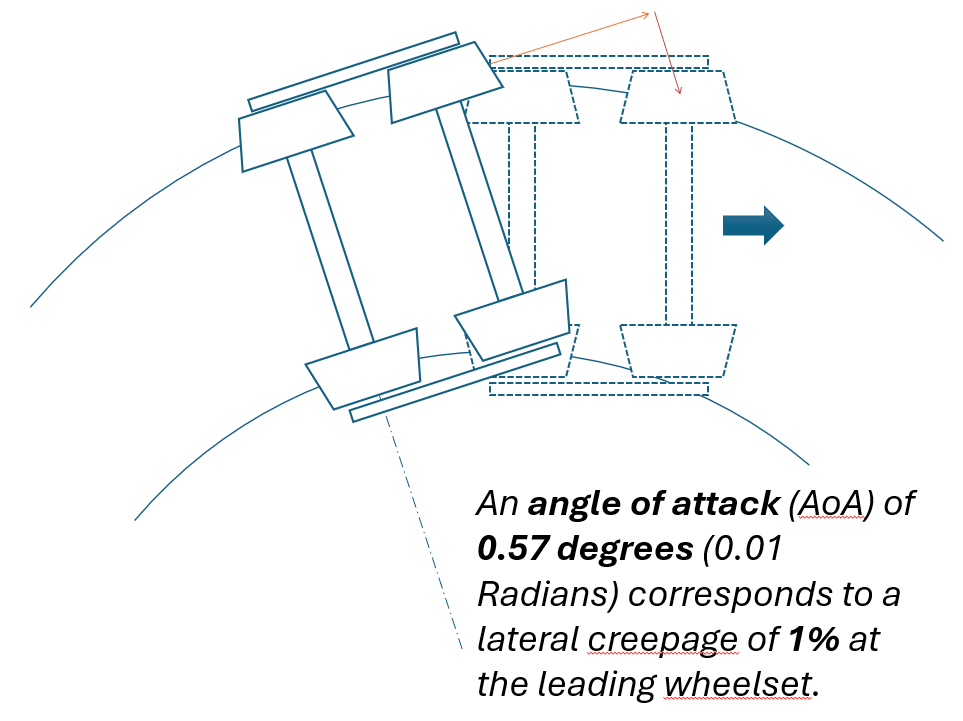
Lateral creepage describes the lateral slip that occurs while the wheel is rolling down the track. “Imagine pushing a lawnmower across a steep slope. You have to apply torque to keep it from slipping down the slope; you’re fighting lateral creepage,” Oldknow said. In the case of wheel/rail interaction, lateral creepage typically occurs in curves. The leading truck, leading wheelset tends to displace toward the high rail, causing gage-corner/flange contact, while the trailing wheelset tends to stay more centered, Oldknow said. That means the truck is developing an angle of attack. For the truck to progress through the curve, the wheelset has to slip laterally (see Figure 11).
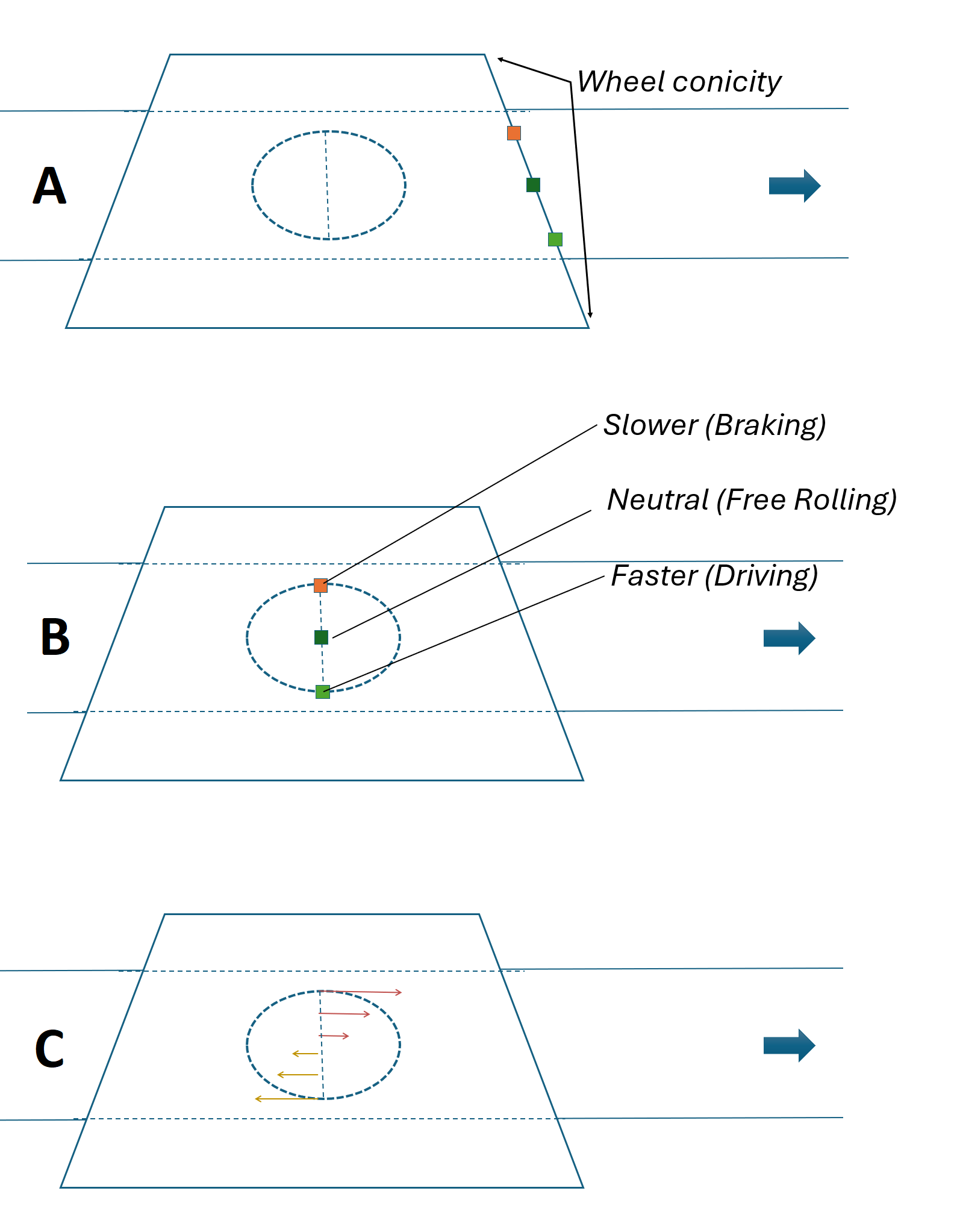
Spin creepage is a function of the conical taper of the wheel and is always occurring at a small amount. Consider three points arranged laterally on a wheel tread. As the wheel rolls, each point will roll over the contact patch at the same time (see Figure 12a and 12b). However, each point is at a different wheel radius and must travel a different distance over the same amount of time, Oldknow said. The smallest radius in the contact patch is moving slower (braking), the neutral point of the contact patch is free rolling, and the largest radius in the contact patch is moving faster (driving). This is what imparts spin creepage (see Figure 12c).
As creepage (longitudinal/lateral/spin) increases, areas of slip develop within the contact patch, Oldknow said. Eventually the traction/creepage, or the friction force, is saturated, and all adhesion is lost. The wheel slips (see Figure 13).
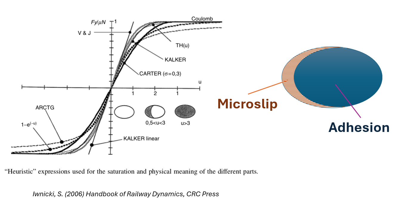
It’s tempting to think of the wheel and rail as two steel bodies in contact with each other, he said, but there is a third body layer between them. It’s primarily composed of wear debris (iron oxides), but it can include environmental debris (leaves, sand, etc.) and deliberately applied materials (lubricants, friction modifiers). The third body layer elastically deforms and (ultimately) shears—producing the adhesion and slip characteristics of traction and creepage.
So, why does a wheelset with an extreme rolling radius difference not rerail itself due to steering forces? The answer is that as the rolling radius increases, so does longitudinal traction/creepage force. Once the force is saturated, there is no “available” friction, and thus there is no steering moment. In practical application, a combination of creepage types (longitudinal/lateral/spin) interact in order to reach the saturation point, but the result is the same. “If the L/V conditions are severe enough to overcome gravity and get the flange onto the top of rail, they’re severe enough to overcome steering,” Oldknow said.
With the introduction of the core principles of wheel/rail interaction: the track, the vehicle, and the contact patch, the complexity of the system is apparent—so is the importance of understanding, engineering, and managing it. Part 2 of this article looks at the second half of the Principles Course, which covers vehicle/track interaction, wheel and rail damage mechanisms, and vehicle and track measurement technologies, along with the conclusion of the derailment case study.

Jeff Tuzik is Managing Editor of Interface Journal
This article is based on a presentation made at the 2026 Wheel/Rail Interaction Heavy Haul Principles Course.